|
|
|
PDF M41ST87W Data sheet ( Hoja de datos )
| Número de pieza | M41ST87W | |
| Descripción | 5.0 V and 3.3/3.0 V secure serial RTC and NVRAM supervisor | |
| Fabricantes | STMicroelectronics | |
| Logotipo | ||
Hay una vista previa y un enlace de descarga de M41ST87W (archivo pdf) en la parte inferior de esta página. Total 52 Páginas | ||
|
No Preview Available !
M41ST87Y
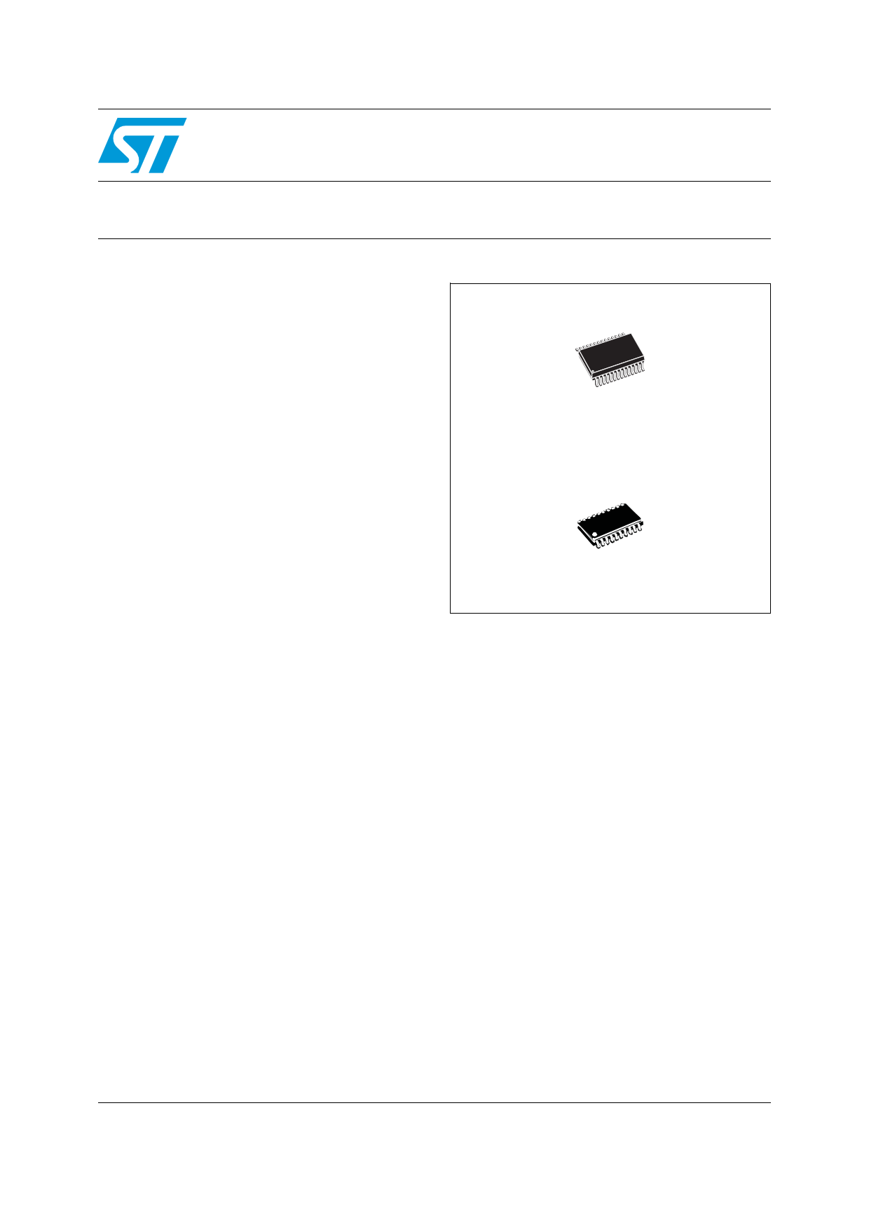
M41ST87W
5.0 V and 3.3/3.0 V secure serial RTC and NVRAM supervisor
with tamper detection and 128 bytes of clearable NVRAM
Features
■ 5.0, 3.3, or 3.0 V operation
■ 400 kHz I2C bus
■ NVRAM supervisor to non-volatize external
LPSRAM
■ 2.5 to 5.5 V oscillator operating voltage
■ Automatic switchover and deselect circuitry
■ Choice of power-fail deselect voltages
– M41ST87Y:
THS = 1: VPFD≈ 4.63 V; VCC = 4.75 to 5.5 V
THS = 0: VPFD≈ 4.37 V; VCC = 4.5 to 5.5 V
– M41ST87W:
THS = 1: VPFD ≈ 2.9 V; VCC = 3.0 to 3.6 V
THS = 0: VPFD ≈ 2.63 V; VCC = 2.7 to 3.6 V
■ Two independent power-fail comparators
(1.25 V reference)
■ Counters for tenths/hundredths of seconds,
seconds, minutes, hours, day, date, month,
year, and century
■ 128 bytes of clearable, general purpose
NVRAM
■ Programmable alarm and interrupt function
(valid even during battery backup mode)
■ Programmable watchdog timer
■ Unique electronic serial number (8-byte)
■ 32 kHz frequency output available upon power-
on
■ Microprocessor power-on reset output
■ Battery low flag
■ Ultra-low battery supply current of 500 nA (typ)
Embedded crystal
28-pin, (300 mil)
SOX28 (MX)
SSOP20 (SS)
Security features
■ Tamper indication circuits with timestamp and
RAM clear
■ LPSRAM clear function (TPCLR)
■ Packaging includes a 28-lead, embedded
crystal SOIC and a 20-lead SSOP
■ Oscillator stop detection
April 2010
www.DataSheet.in
Doc ID 9497 Rev 8
1/52
www.st.com
1
1 page 
M41ST87Y, M41ST87W
List of figures
List of figures
Figure 1.
Figure 2.
Figure 3.
Figure 4.
Figure 5.
Figure 6.
Figure 7.
Figure 8.
Figure 9.
Figure 10.
Figure 11.
Figure 12.
Figure 13.
Figure 14.
Figure 15.
Figure 16.
Figure 17.
Figure 18.
Figure 19.
Figure 20.
Figure 21.
Figure 22.
Figure 23.
Figure 24.
Figure 25.
Figure 26.
Figure 27.
Figure 28.
Figure 29.
Figure 30.
Logic diagram . . . . . . . . . . . . . . . . . . . . . . . . . . . . . . . . . . . . . . . . . . . . . . . . . . . . . . . . . . . . 7
28-pin, 300 mil SOIC (MX) connections . . . . . . . . . . . . . . . . . . . . . . . . . . . . . . . . . . . . . . . . 8
20-pin, SSOP (SS) connections . . . . . . . . . . . . . . . . . . . . . . . . . . . . . . . . . . . . . . . . . . . . . . 8
Block diagram . . . . . . . . . . . . . . . . . . . . . . . . . . . . . . . . . . . . . . . . . . . . . . . . . . . . . . . . . . . 10
Hardware hookup . . . . . . . . . . . . . . . . . . . . . . . . . . . . . . . . . . . . . . . . . . . . . . . . . . . . . . . . 11
Serial bus data transfer sequence . . . . . . . . . . . . . . . . . . . . . . . . . . . . . . . . . . . . . . . . . . . 14
Acknowledgement sequence . . . . . . . . . . . . . . . . . . . . . . . . . . . . . . . . . . . . . . . . . . . . . . . 14
Bus timing requirements sequence . . . . . . . . . . . . . . . . . . . . . . . . . . . . . . . . . . . . . . . . . . 14
Slave address location . . . . . . . . . . . . . . . . . . . . . . . . . . . . . . . . . . . . . . . . . . . . . . . . . . . . 16
READ mode sequence . . . . . . . . . . . . . . . . . . . . . . . . . . . . . . . . . . . . . . . . . . . . . . . . . . . . 16
Alternate READ mode sequence . . . . . . . . . . . . . . . . . . . . . . . . . . . . . . . . . . . . . . . . . . . . 16
WRITE mode sequence . . . . . . . . . . . . . . . . . . . . . . . . . . . . . . . . . . . . . . . . . . . . . . . . . . . 17
WRITE cycle timing: RTC & external SRAM control signals. . . . . . . . . . . . . . . . . . . . . . . . 17
Tamper detect connection options . . . . . . . . . . . . . . . . . . . . . . . . . . . . . . . . . . . . . . . . . . . 20
Basic tamper detect options . . . . . . . . . . . . . . . . . . . . . . . . . . . . . . . . . . . . . . . . . . . . . . . . 21
Tamper detect output options . . . . . . . . . . . . . . . . . . . . . . . . . . . . . . . . . . . . . . . . . . . . . . . 21
Tamper detect sampling options. . . . . . . . . . . . . . . . . . . . . . . . . . . . . . . . . . . . . . . . . . . . . 23
Tamper current options. . . . . . . . . . . . . . . . . . . . . . . . . . . . . . . . . . . . . . . . . . . . . . . . . . . . 24
Tamper output timing (with CLR1EXT or CLR2EXT = '1') - available in
SOX28 (MX) package only . . . . . . . . . . . . . . . . . . . . . . . . . . . . . . . . . . . . . . . . . . . . . . . . . 24
RAM clear hardware hookup (SOX28 MX package only). . . . . . . . . . . . . . . . . . . . . . . . . . 25
Low-pass filter implementation for noise immunity . . . . . . . . . . . . . . . . . . . . . . . . . . . . . . . 27
Crystal accuracy across temperature . . . . . . . . . . . . . . . . . . . . . . . . . . . . . . . . . . . . . . . . . 33
Calibration waveform . . . . . . . . . . . . . . . . . . . . . . . . . . . . . . . . . . . . . . . . . . . . . . . . . . . . . 33
Alarm interrupt reset waveform. . . . . . . . . . . . . . . . . . . . . . . . . . . . . . . . . . . . . . . . . . . . . . 34
Backup mode alarm waveform . . . . . . . . . . . . . . . . . . . . . . . . . . . . . . . . . . . . . . . . . . . . . . 35
RSTIN1 & RSTIN2 timing waveforms . . . . . . . . . . . . . . . . . . . . . . . . . . . . . . . . . . . . . . . . . 37
AC testing input/output waveforms . . . . . . . . . . . . . . . . . . . . . . . . . . . . . . . . . . . . . . . . . . . 43
Power down/up mode AC waveforms. . . . . . . . . . . . . . . . . . . . . . . . . . . . . . . . . . . . . . . . . 46
SOX28 – 28-lead plastic small outline, 300 mils, embedded crystal outline. . . . . . . . . . . . 47
SSOP20 – 20-lead, shrink, small outline package outline . . . . . . . . . . . . . . . . . . . . . . . . . 48
www.DataSheet.in
Doc ID 9497 Rev 8
5/52
5 Page 
M41ST87Y, M41ST87W
Figure 5. Hardware hookup
Unregulated
Voltage
VIN VCC
5V
Regulator
VIN VCC
3.3V
Regulator
For monitoring
of additional
voltage sources
Pushbutton
R1 R3 Reset
R2
R4
1. Available in SOX28 (MX) package only.
Description
M41ST87Y/W
VCC
(1)
TPCLR
TP1IN
TP2IN
VOUT
ECON(1)
EX (1)
SCL
WDI(1)
SDA
RSTIN1
(1)
RSTIN2
PFI1
PFI2
VSS
VBAT
RST
SQW/FT
PFO1
PFO2
IRQ/OUT
F32k
VCC
E
Low-Power
SRAM
To Microprocessor
To LED Display
To NMI
To INT
To 32kHz
AI07027
www.DataSheet.in
Doc ID 9497 Rev 8
11/52
11 Page | ||
| Páginas | Total 52 Páginas | |
| PDF Descargar | [ Datasheet M41ST87W.PDF ] | |
Hoja de datos destacado
| Número de pieza | Descripción | Fabricantes |
| M41ST87W | 5.0 V and 3.3/3.0 V secure serial RTC and NVRAM supervisor | STMicroelectronics |
| M41ST87Y | 5.0 V and 3.3/3.0 V secure serial RTC and NVRAM supervisor | STMicroelectronics |
| Número de pieza | Descripción | Fabricantes |
| SLA6805M | High Voltage 3 phase Motor Driver IC. |
Sanken |
| SDC1742 | 12- and 14-Bit Hybrid Synchro / Resolver-to-Digital Converters. |
Analog Devices |
|
DataSheet.es es una pagina web que funciona como un repositorio de manuales o hoja de datos de muchos de los productos más populares, |
| DataSheet.es | 2020 | Privacy Policy | Contacto | Buscar |