|
|
|
PDF RT9214 Data sheet ( Hoja de datos )
| Número de pieza | RT9214 | |
| Descripción | 5V/12V Synchronous Buck PWM DC-DC Controller | |
| Fabricantes | Richtek Technology | |
| Logotipo | ||
Hay una vista previa y un enlace de descarga de RT9214 (archivo pdf) en la parte inferior de esta página. Total 16 Páginas | ||
|
No Preview Available !
5Vh/e1e2tV4US.cyonmchronous Buck PWM DC-DC CoRnTtr9o2l1le4rGeneral Description
taSThe RT9214 is a high efficiency synchronous buck PWM
acontrollers that generate logic-supply voltages in PC based
.Dsystems. These high performance , single output devices
winclude internal soft-start, frequency compensation
wnetworks and integrates all of the control, output
wadjustment, monitoring and protection functions into a
Features
z Operating with 5V or 12V Supply Voltage
z Drives All Low Cost N-Channel MOSFETs
z Voltage Mode PWM Control
z 300kHz Fixed Frequency Oscillator
z Fast Transient Response:
− High-Speed GM Amplifier
single package.
The device operating at fixed 300kHz frequency provides
man optimum compromise between efficiency, external
ocomponent size, and cost.
.cAdjustable over-current protection (OCP) monitors the
voltage drop across the RDS(ON) of the lower MOSFET for
Usynchronous buck PWM DC-DC controller. The over-
t4current function cycles the soft-start in 4-times hiccup
mode to provide fault protection, and in an always hiccup
emode for under-voltage protection.
− Full 0 to 100% Duty Ratio
z Internal Soft-Start
z Adaptive Non-Overlapping Gate Driver
z Over-Current Fault Monitor on MOSFET, No
Current Sense Resistor Required
Applications
z Graphic Card
z Motherboard, Desktop Servers
z IA Equipments
z Telecomm Equipments
z High Power DC-DC Regulators
eOrdering Information
hRT9214
SPackage Type
S : SOP-8
taOperating Temperature Range
C : Commercial Standard
aP : Pb Free with Commercial Standard
Pin Configurations
(TOP VIEW)
BOOT
UGATE
GND
LGATE
2
3
4
8 PHASE
7 OPS
6 FB
5 VCC
SOP-8
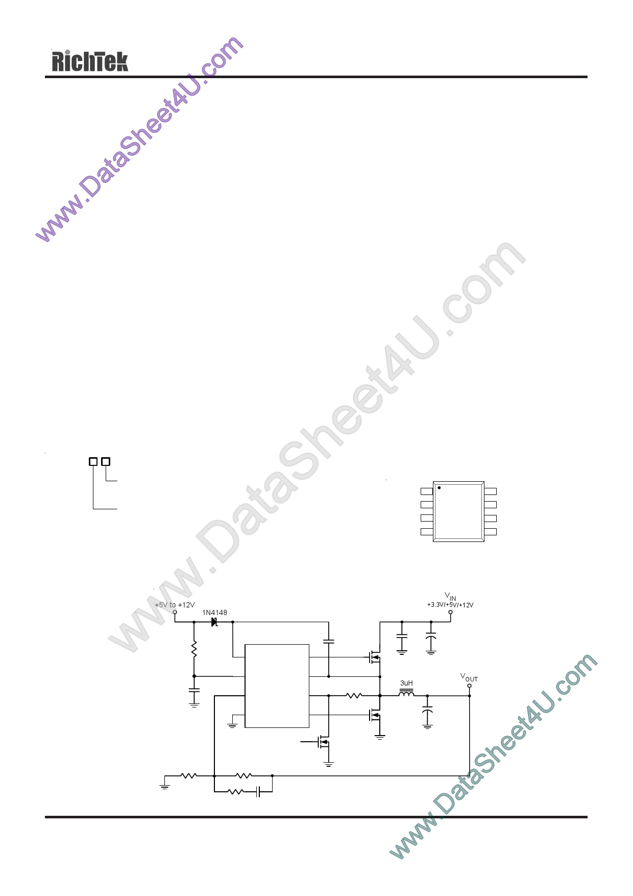
.DTypical Application Circuit
w+5V to +12V D1
1N4148
VIN
+3.3V/+5V/+12V
w R1
10
w omC1
U.c1uF
1 BOOT UGATE 2
5 VCC
PHASE 8
6
FB
RT9214
OPS
7
3 GND
LGATE 4
C2
0.1uF
ROCSET
C3
1uF
Q1
MU
L1
3uH
C4
470uF
VOUT
C6 to C8
Q2 1000uFx3
ML
et4Disable >
Q3
2N7002
heR2 R3
32 68
www.DataSDS9214-02 December 2004
R4 C5
200-1k 0.1-0.33uF
www.richtek.com
1
1 page 
RT9214
Parameter
Symbol
Test Conditions
Min Typ Max Units
Error Amplifier (GM)
E/A Transconductance
gm
Open Loop DC Gain
AO
PWM Controller Gate Drivers (VCC = 12V)
Upper Gate Source
IUGATE
Upper Gate Sink
Lower Gate Source
Lower Gate Sink
Dead Time
RUGATE
ILGATE
RLGATE
TDT
VBOOT − VPHASE = 12V,
VUGATE − VPHASE = 6V
VBOOT − VPHASE = 12V,
VUGATE − VPHASE = 1V
VCC = 12V, VLGATE = 6V
VCC = 12V, VLGATE = 1V
-- 0.7 --
-- 90 --
ms
dB
300 500 -- mA
-- 4 8
300 500 --
-- 3 5
-- -- 100
Ω
mA
Ω
ns
Protection
FB Under-Voltage Trip
OC Current Source
Soft-Start Interval
∆ FBUVT
IOC
TSS
FB Falling
VPHASE = 0V
70 75 80
35 40 45
-- 3.5 --
%
µA
ms
Note 1. Stresses listed as the above "Absolute Maximum Ratings" may cause permanent damage to the device. These are for
stress ratings. Functional operation of the device at these or any other conditions beyond those indicated in the
operational sections of the specifications is not implied. Exposure to absolute maximum rating conditions for extended
periods may remain possibility to affect device reliability.
Note 2. Devices are ESD sensitive. Handling precaution recommended.
Note 3. The device is not guaranteed to function outside its operating conditions.
Note 4. θJA is measured in the natural convection at TA = 25°C on a low effective thermal conductivity test board of
JEDEC 51-3 thermal measurement standard.
DS9214-02 December 2004
www.richtek.com
5
5 Page 
RT9214
OPS (Over Current Setting, VIN_POR and Shutdown)
1.OCP
Sense the low-side MOSFET’ s RDS(ON) to set over-current trip point.
Connecting a resistor (ROCSET) from this pin to the source of the upper MOSFET and the drain of the lower MOSFET
sets the over-current trip point. ROCSET, an internal 40µA current source, and the lower MOSFET on resistance, RDS(ON),
set the converter over-current trip point (IOCSET) according to the following equation:
IOCSET
40uA × ROCSET − 0.4V
R=
DS(ON)
of
the lower
MOSFET
OPS pin function is similar to RC charging or discharging circuit, so the over-current trip point is very sensitive to
parasitic capacitance (ex. shut-down MOSFET) and the duty ratio.
Below Figures say those effect. And test conditions are Rocset = 15kΩ (over -current trip point = 20.6A), Low-side
MOSFET is IR3707.
OCP
OCP
UGATE (10V/Div)
IL (10A/Div)
VIN = 5V, VCC = 12V
VOUT = 1.5V
Time (5µs/Div)
OCP
UGATE (10V/Div)
IL (10A/Div)
VIN = 12V, VCC = 12V
VOUT = 1.5V
Time (2.5µs/Div)
DS9214-02 December 2004
UGATE
(10V/Div)
OPS (200mV/Div)
VIN = 5V, VCC = 12V
VOUT = 1.5V
Time (5µs/Div)
IL (10A/Div)
OCP
OPS
(200mV/Div)
UGATE
(10V/Div)
VIN = 12V, VCC = 12V
VOUT = 1.5V
Time (2.5µs/Div)
IL (10A/Div)
www.richtek.com
11
11 Page | ||
| Páginas | Total 16 Páginas | |
| PDF Descargar | [ Datasheet RT9214.PDF ] | |
Hoja de datos destacado
| Número de pieza | Descripción | Fabricantes |
| RT9212 | Dual 5V Synchronous Buck PWM DC-DC and Linear Power Controller | RichTek |
| RT9214 | 5V/12V Synchronous Buck PWM DC-DC Controller | Richtek Technology |
| RT9216B | VFM STEP UP DC/DC CONVERTER | RichTek |
| RT9216B-xxx | VFM STEP UP DC/DC CONVERTER | RichTek |
| Número de pieza | Descripción | Fabricantes |
| SLA6805M | High Voltage 3 phase Motor Driver IC. |
Sanken |
| SDC1742 | 12- and 14-Bit Hybrid Synchro / Resolver-to-Digital Converters. |
Analog Devices |
|
DataSheet.es es una pagina web que funciona como un repositorio de manuales o hoja de datos de muchos de los productos más populares, |
| DataSheet.es | 2020 | Privacy Policy | Contacto | Buscar |