|
|
|
PDF LTM8008 Data sheet ( Hoja de datos )
| Número de pieza | LTM8008 | |
| Descripción | DC/DC SEPIC uModule Regulator | |
| Fabricantes | Linear | |
| Logotipo | ||
Hay una vista previa y un enlace de descarga de LTM8008 (archivo pdf) en la parte inferior de esta página. Total 16 Páginas | ||
|
No Preview Available !
LTM8008
72VIN, 6 Output DC/DC
SEPIC µModule Regulator
Features
n One SEPIC Converter with Six Linear Regulators
n Wide Input Voltage Range: 3V to 72V, 6V Start
n Wide Operating Temperature: –40°C to 150°C
(H-Grade)
n Current Mode Control Provides Excellent Transient
Response
n Programmable Operating Frequency
(100kHz to 1MHz) with One External Resistor
n Synchronizeable to an External Clock
n Programmable Input Undervoltage Lockout with
Hysteresis
n Programmable Soft-Start
n Small 15mm × 15mm × 2.82mm LGA Package
Applications
n Automotive Converters
n Industrial Converters
n Telecom Power Supplies
L, LT, LTC, LTM, Linear Technology, the Linear logo and µModule are registered trademarks of
Linear Technology Corporation. All other trademarks are the property of their respective owners.
Description
The LTM®8008 is a 72VIN, µModule® SEPIC converter with
six post regulators. The SEPIC controller’s fixed frequency,
current-mode architecture results in stable operation over
a wide range of supply and output voltages and features
soft-start and frequency foldback functions to limit inductor
current during start-up and output short-circuit.
The LTM8008 also includes six high performance, fixed
output LDOs for post-regulation: one 5V at 500mA, one
3.3V at 300mA, and four 5V at 150mA. The output of the
SEPIC controller is internally set to 5.6V for optimal ef-
ficiency. In addition to providing these outputs, the SEPIC
converter can supply up to an additional 500mA to the
system load.
The LTM8008 is packaged in a thermally enhanced, compact
(15mm × 15mm) and low profile (2.82mm) over-molded
land grid array (LGA) package suitable for automated
assembly by standard surface mount equipment. The
LTM8008 is Pb-free and RoHS compliant.
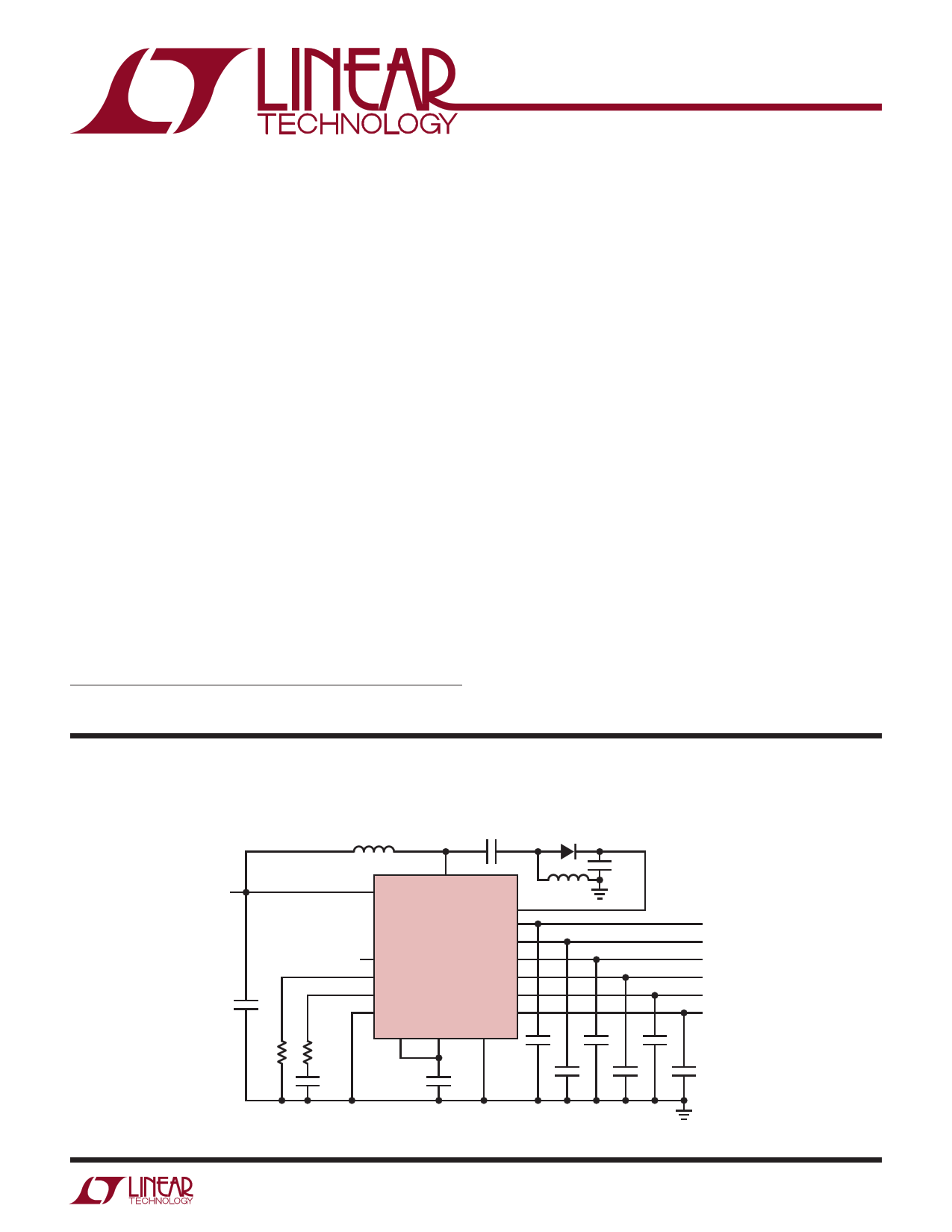
Typical Application
Six Output DC/DC µModule Regulator
L1A
4.7µH
10µF
SBR3U100LP-7
VIN
3V TO 72V
4.7µF
42.2k
4.99k
22nF
VIN
SS
RT
VC
SYNC
RUN
SW
SPV
VOUT1
LTM8008
VOUT2
VOUT3
VOUT4
VOUT5
VOUT6
INTVCC GND
4.7µF
L1: COUPLED INDUCTOR, COILCRAFT MSD1278T-472ML
L1B
4.7µH
5V AT 500mA
5V AT 150mA
5V AT 150mA
5V AT 150mA
5V AT 150mA
3.3V AT 300mA
22µF
10µF
10µF
10µF
10µF
10µF
8008 TA01
8008fa
1
1 page 
Typical Performance Characteristics
vVsOUTTe2m,3p,4e,r5aCtuurrerent Limit
600
500
SHORT-CIRCUIT
400
VOUT DROPS 1%
300
200
100
0
–40 –20 0
20 40 60 80 100 120 140
TEMPERATURE (°C)
8008 G10
vVsOUTTe6mCpuerrraetnutreLimit
1000
900
800 SHORT-CIRCUIT
700
600 VOUT DROPS 1%
500
400
300
200
100
0
–40 –20 0
20 40 60 80 100 120 140
TEMPERATURE (°C)
8008 G11
LTM8008
V(NINo
Pin Current
Load)
vs
Temperature
150
140
24VIN
130
120
110
100
90
80
12VIN
70
60
–40 –20 0
20 40 60 80 100 120 140
TEMPERATURE (°C)
8008 G12
RUN Threshold vs Temperature
1.210
1.205
1.200
1.195
1.190
–40 –20 0
20 40 60 80 100 120 140
TEMPERATURE (°C)
8008 G13
Input Current vs Percentage of
LDO Load (Front Page Schematic)
900
800
700
600 12VIN
500
400
300
200 24VIN
100
0
0 20 40 60 80 100
MAXIMUM RATED LDO LOAD (%)
8008 G15
Run Current vs Run Voltage
25
20
15
10
5
0
0 2 4 6 8 10
RUN VOLTAGE (V)
8008 G14
Temperature Rise vs Percentage
of LDO Load (Front Page
Schematic, Measured on
DC1630A Demo Board)
35
30
25 12VIN
20 24VIN
15
10
5
0
0 20 40 60 80 100
MAXIMUM RATED LDO LOAD (%)
8008 G16
8008fa
5
5 Page 
LTM8008
Applications Information
4. Connect all of the GND connections to as large a copper
pour or plane area as possible on the top layer. Avoid
breaking the ground connection between the external
components and the LTM8008.
5. For good heatsinking, use vias to connect the GND cop-
per area to the board’s internal ground planes. Liberally
distribute these GND vias to provide both a good ground
connection and thermal path to the internal planes of the
printed circuit board. Pay attention to the location and
density of the thermal vias in Figure 3. The LTM8008
can benefit from the heat-sinking afforded by vias that
connect to internal GND planes at these locations, due to
their proximity to internal power handling components.
The optimum number of thermal vias depends upon
the printed circuit board design. For example, a board
might use very small via holes. It should employ more
thermal vias than a board that uses larger holes.
Post Regulator Output Capacitance and Transient
Response
The LTM8008 linear post regulators are designed to be
stable with a wide range of output capacitors. The ESR
of the output capacitor affects stability, most notably with
small capacitors. The output transient response will be a
function of output capacitance. Larger values of output
capacitance decrease the peak deviations and provide im-
proved transient response for larger load current changes.
Bypass capacitors, used to decouple individual components
powered by the post regulators, will increase the effective
output capacitor value. Extra consideration must be given
to the use of ceramic capacitors. Ceramic capacitors are
manufactured with a variety of dielectrics, each with dif-
ferent behavior across temperature and applied voltage.
The most common dielectrics used are specified with EIA
temperature characteristic codes of Z5U, Y5V, X5R and
LDO OUTPUT CAPACITOR
GND
SPV SW
L1
COUPLED
INDUCTOR
VIN
LDO
OUTPUT
CAPACITORS
FLYING
CAPACITOR
CIN
VIN
POWER
DIODE
SPV
SPV
GND
CINTVCC
CONTROL DISCRETES
COUT COUT
Figure 3. Layout Showing Suggested External Components, GND Plane and Interconnect/Thermal Vias
8008fa
11
11 Page | ||
| Páginas | Total 16 Páginas | |
| PDF Descargar | [ Datasheet LTM8008.PDF ] | |
Hoja de datos destacado
| Número de pieza | Descripción | Fabricantes |
| LTM8001 | 5A uModule Regulator | Linear Technology |
| LTM8008 | DC/DC SEPIC uModule Regulator | Linear |
| Número de pieza | Descripción | Fabricantes |
| SLA6805M | High Voltage 3 phase Motor Driver IC. |
Sanken |
| SDC1742 | 12- and 14-Bit Hybrid Synchro / Resolver-to-Digital Converters. |
Analog Devices |
|
DataSheet.es es una pagina web que funciona como un repositorio de manuales o hoja de datos de muchos de los productos más populares, |
| DataSheet.es | 2020 | Privacy Policy | Contacto | Buscar |