|
|
|
PDF DMG4511SK4 Data sheet ( Hoja de datos )
| Número de pieza | DMG4511SK4 | |
| Descripción | COMPLEMENTARY PAIR ENHANCEMENT MODE MOSFET | |
| Fabricantes | Diodes | |
| Logotipo | ||
Hay una vista previa y un enlace de descarga de DMG4511SK4 (archivo pdf) en la parte inferior de esta página. Total 9 Páginas | ||
|
No Preview Available !
DMG4511SK4
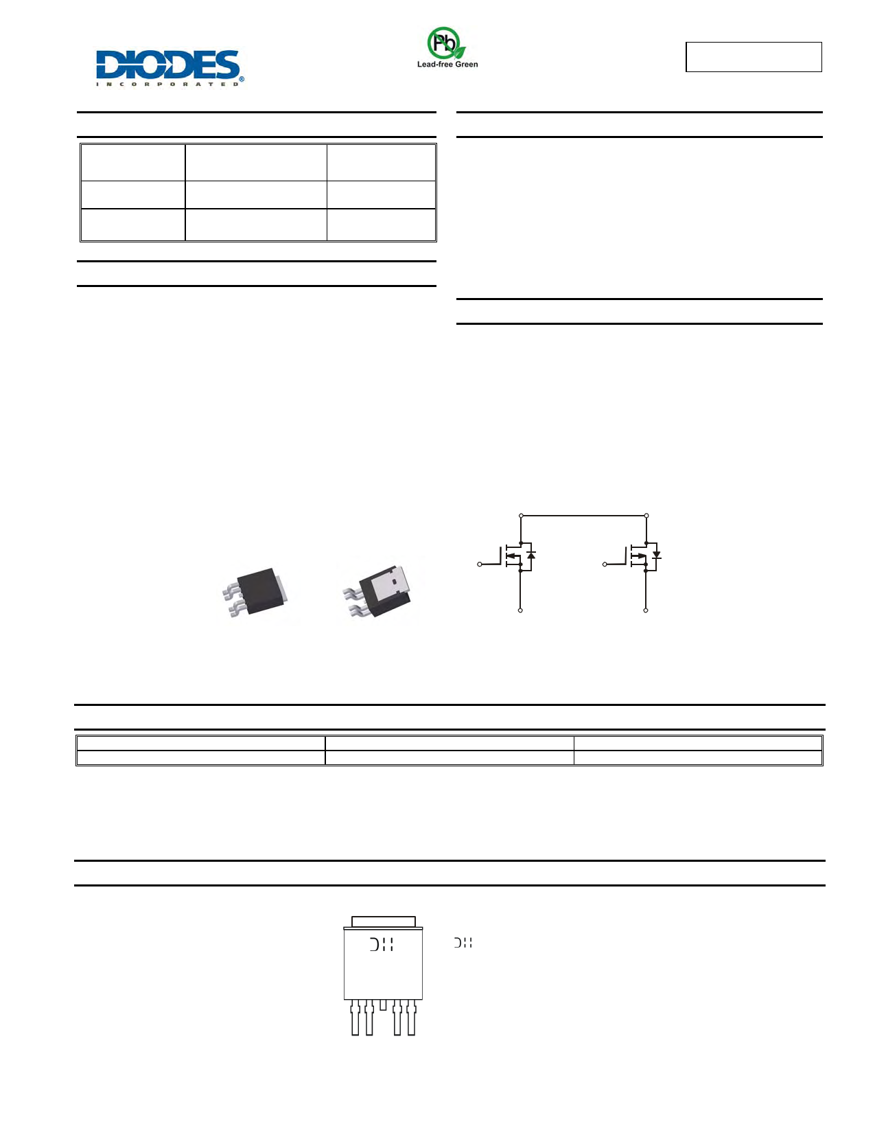
COMPLEMENTARY PAIR ENHANCEMENT MODE MOSFET
Product Summary
V(BR)DSS
35V
-35V
RDS(ON)
35mΩ @ VGS = 10V
45mΩ @ VGS = -10V
ID
TA = 25°C
13A
-12A
Description and Applications
This new generation MOSFET has been designed to minimize the on-
state resistance (RDS(on)) and yet maintain superior switching
performance, making it ideal for high efficiency power management
applications.
• Backlighting
• DC-DC Converters
• Power management functions
Features and Benefits
• Low On-Resistance
• Low Gate Threshold Voltage
• Low Input Capacitance
• Fast Switching Speed
• Low Input/Output Leakage
• Complementary Pair MOSFET
• Lead Free/RoHS Compliant (Note 1)
• "Green" Device (Note 2)
• Qualified to AEC-Q101 Standards for High Reliability
Mechanical Data
• Case: TO252-4L
• Case Material: Molded Plastic, “Green” Molding Compound. UL
Flammability Classification Rating 94V-0
• Moisture Sensitivity: Level 1 per J-STD-020
• Terminal Connections: See Diagram Below
• Terminals: Finish – Matte Tin annealed over Copper leadframe.
Solderable per MIL-STD-202, Method 208
• Weight: 0.328 grams (approximate)
Top View
Bottom View
D2 D1
G2 G1
S2 S1
N-Channel MOSFET P-Channel MOSFET
Ordering Information (Note 3)
Notes:
Part Number
DMG4511SK4-7
Case
TO252-4L
1. No purposefully added lead.
2. Diodes Inc.'s "Green" policy can be found on our website at http://www.diodes.com.
3. For packaging details, go to our website at http://www.diodes.com.
Packaging
3000 / Tape & Reel
Marking Information
G4511S
YYWW
= Manufacturer’s Marking
G4511S = Product Type Marking Code
YYWW = Date Code Marking
YY = Year (ex: 09 = 2009)
WW = Week (01 – 53)
DMG4511SK4
Document number: DS32042 Rev. 4 - 2
1 of 9
www.diodes.com
July 2011
© Diodes Incorporated
1 page 
DMG4511SK4
3.0
2.7
2.4
2.1
1.8
1.5 ID = 250µA
1.2
0.9
0.6
0.3
0
-50 -25 0 25 50 75 100 125 150
TA, AMBIENT TEMPERATURE (°C)
Fig. 7 Gate Threshold Variation vs. Ambient Temperature
1,400
20
18
16
14 TA = 25°C
12
10
8
6
4
2
0
0.2 0.4 0.6 0.8 1.0 1.2
VSD, SOURCE-DRAIN VOLTAGE (V)
Fig. 8 Diode Forward Voltage vs. Current
10,000
1,200
1,000
800
600
Ciss
f = 1MHz
1,000
100
TA = 150°C
TA = 125°C
TA = 85°C
400
200
0
0
Coss
Crss
5 10 15 20 25 30
VDS, DRAIN-SOURCE VOLTAGE (V)
Fig. 9 Typical Total Capacitance
35
1
D = 0.7
D = 0.5
D = 0.3
10 TA = 25°C
1
5 10 15 20 25 30 35
VDS, DRAIN-SOURCE VOLTAGE (V)
Fig. 10 Typical Leakage Current
vs. Drain-Source Voltage
0.1
D = 0.1
D = 0.05
D = 0.02
0.01
D = 0.01
D = 0.005
D = Single Pulse
0.001
0.00001 0.0001
0.001
D = 0.9
RθJA(t) = r(t) * RθJA
RθJA = 80°C/W
P(pk)
t1
t2
TJ - TA = P * RθJA(t)
Duty Cycle, D = t1/t2
0.01
0.1
1
t1, PULSE DURATION TIME (s)
Fig. 11 Transient Thermal Response
10
100
1,000
DMG4511SK4
Document number: DS32042 Rev. 4 - 2
5 of 9
www.diodes.com
July 2011
© Diodes Incorporated
5 Page | ||
| Páginas | Total 9 Páginas | |
| PDF Descargar | [ Datasheet DMG4511SK4.PDF ] | |
Hoja de datos destacado
| Número de pieza | Descripción | Fabricantes |
| DMG4511SK4 | COMPLEMENTARY PAIR ENHANCEMENT MODE MOSFET | Diodes |
| Número de pieza | Descripción | Fabricantes |
| SLA6805M | High Voltage 3 phase Motor Driver IC. |
Sanken |
| SDC1742 | 12- and 14-Bit Hybrid Synchro / Resolver-to-Digital Converters. |
Analog Devices |
|
DataSheet.es es una pagina web que funciona como un repositorio de manuales o hoja de datos de muchos de los productos más populares, |
| DataSheet.es | 2020 | Privacy Policy | Contacto | Buscar |