|
|
|
PDF NX2124 Data sheet ( Hoja de datos )
| Número de pieza | NX2124 | |
| Descripción | 300kHz SYNCHRONOUS PWM CONTROLLER | |
| Fabricantes | Microsemi | |
| Logotipo | ||
Hay una vista previa y un enlace de descarga de NX2124 (archivo pdf) en la parte inferior de esta página. Total 17 Páginas | ||
|
No Preview Available !
Evaluation board available.
NX2124/2124A
300kHz SYNCHRONOUS PWM CONTROLLER
PRODUCTION DATA SHEET
Pb Free Product
DESCRIPTION
FEATURES
The NX2124/2124A controller IC is a synchronous Buck
controller IC designed for step down DC to DC con-
verter applications. It is optimized to convert bus volt-
ages from 2V to 25V to outputs as low as 0.8V voltage.
n
n
n
n
Bus voltage operation from 2V to 25V
Fixed 300kHz voltage mode controller
Internal Digital Soft Start Function
Prebias Startup
The NX2124/2124A operates at fixed 300kHz, employs n Less than 50 nS adaptive deadband
fixed loss-less current limiting by sensing the Rdson of n Current limit triggers hiccup by sensing Rdson of
synchronous MOSFET followed by hiccup feature.
NX2124A has higher current limit threshold than NX2124.
n
Synchronous MOSFET
No negative spike at Vout during startup and
Feedback under voltage also triggers hiccup.
Other features of the device are: 5V gate drive, Adaptive
n
shutdown
Pb-free and RoHS compliant
deadband control, Internal digital soft start, Vcc
APPLICATIONS
undervoltage lock out and shutdown capability via the
comp pin.
n
n
Graphic Card on board converters
Memory Vddq Supply in mother board applications
n On board DC to DC such as
5V to 3.3V, 2.5V or 1.8V
n Hard Disk Drive
n Set Top Box
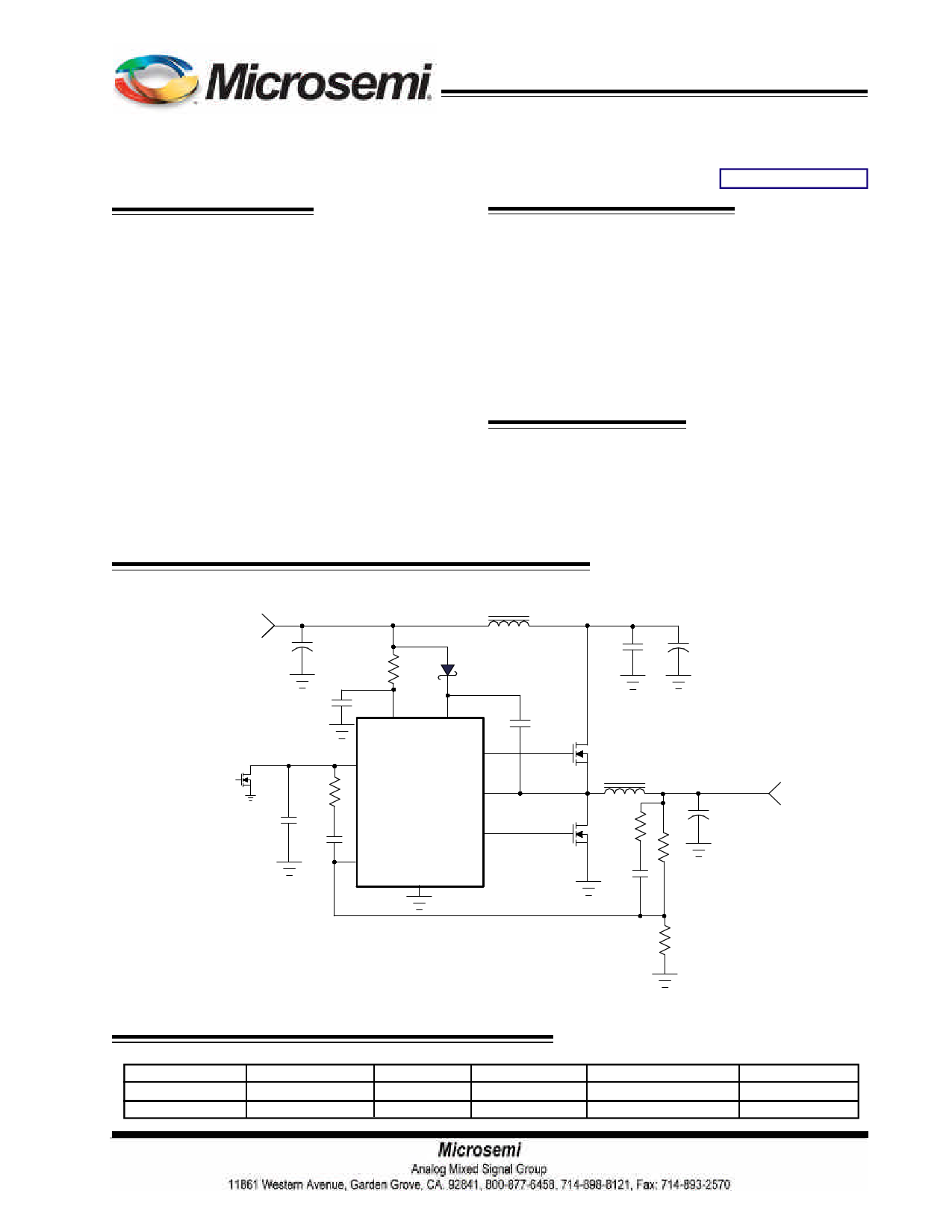
TYPICAL APPLICATION
Vin
+5V
HI=SD
M3
C7
27pF
L2 1uH
C4
100uF
R5 D1
10 MBR0530T1
C3
1uF 5
Vcc
R4
37.4k
7 COMP
1
BST
Hdrv 2
SW 8
C6
0.1uF
C2
2.2nF
6 FB
Ldrv 4
Gnd
3
C5 Cin
1uF 280uF
18mohm
M1
L1 1.5uH
M2
R1
4k
Vout
+1.8V 9A
Co
2 x (1500uF,13mohm)
C1
4.7nF
R2
10k
R3
8k
Figure1 - Typical application of 2124
ORDERING INFORMATION
Device
NX2124CSTR
NX2124ACSTR
Temperature
0 to 70 oC
0 to 70o C
Package
SOIC-8L
SOIC-8L
Frequency
300kHz
300kHz
OCP Threshold
360mV
540mV
Pb-Free
Yes
Yes
Rev.1.9
06/12/12
1
1 page 
BLOCK DIAGRAM
NX2124/2124A
VCC 70%Vp
FB
Bias
Generator
1.25V
0.8V
UVLO
POR
FB
COMP
COMP
0.3V
START 0.8V
Digital
start Up
OSC
ramp
OC
SQ
R
START
0.6V
CLAMP
1.3V
CLAMP
GND
Hiccup Logic
OC
START
PWM
Control
Logic
VCC
BST
HDRV
SW
LDRV
Hiccup Logic
360mV/540mV
OCP
comparator
Figure 2 - Simplified block diagram of the NX2124/NX2124A
Rev.1.9
06/12/12
5
5 Page 
NX2124/2124A
B. Type II compensator design
If the electrolytic capacitors are chosen as power
stage output capacitors, usually the Type II compensa-
tor can be used to compensate the system.
Type II compensator can be realized by simple RC
circuit without feedback as shown in figure 6. R3 and C1
introduce a zero to cancel the double pole effect. C2
introduces a pole to suppress the switching noise. The
following equations show the compensator pole zero lo-
cation and constant gain.
Vout
R2
Fb
R1
Vref
gm
Ve
R3
C2
C1
Gain=gm
×
R1
R1+R2
× R3
Fz
=
2
×
π
1
× R3
×
C1
Fp
≈
1
2 × π ×R3
× C2
... (15)
... (16)
... (17)
power stage
40dB/decade
loop gain
20dB/decade
Figure 7 - Type II compensator with
transconductance amplifier
For this type of compensator, FO has to satisfy
FLC<FESR<<FO<=1/10~1/5Fs.
The following is parameters for type II compensa-
tor design. Input voltage is 5V, output voltage is 1.8V,
output inductor is 1.5uH, output capacitors are two
1500uF with 13mΩ electrolytic capacitors.
1.Calculate the location of LC double pole F
LC
and ESR zero F .
ESR
FLC = 2 × π ×
1
LOUT × COUT
=1
2 × π × 1.5uH× 3000uF
= 2.3kHz
compensator
Gain
FZ FLCFESR FO FP
Figure 6 - Bode plot of Type II compensator
FESR
=
1
2 × π × ESR × COUT
=1
2 × π × 6.5mΩ × 3000uF
= 8.2kHz
2.Set R2 equal to 1kΩ.
R1
=
R2 ×
VOUT
VREF
-VREF
= 1kΩ × 0.8V
1.8V-0.8V
= 800Ω
Choose R1=800Ω.
3. Set crossover frequency at 1/10~ 1/5 of the
swithing frequency, here FO=30kHz.
4.Calculate R3 value by the following equation.
Rev.1.9
06/12/12
11
11 Page | ||
| Páginas | Total 17 Páginas | |
| PDF Descargar | [ Datasheet NX2124.PDF ] | |
Hoja de datos destacado
| Número de pieza | Descripción | Fabricantes |
| NX2124 | 300kHz SYNCHRONOUS PWM CONTROLLER | Microsemi |
| NX2124A | 300kHz SYNCHRONOUS PWM CONTROLLER | Microsemi |
| Número de pieza | Descripción | Fabricantes |
| SLA6805M | High Voltage 3 phase Motor Driver IC. |
Sanken |
| SDC1742 | 12- and 14-Bit Hybrid Synchro / Resolver-to-Digital Converters. |
Analog Devices |
|
DataSheet.es es una pagina web que funciona como un repositorio de manuales o hoja de datos de muchos de los productos más populares, |
| DataSheet.es | 2020 | Privacy Policy | Contacto | Buscar |