|
|
|
PDF APL5606A Data sheet ( Hoja de datos )
| Número de pieza | APL5606A | |
| Descripción | Low Dropout 600mA Linear Regulator | |
| Fabricantes | ANPEC | |
| Logotipo | ||
Hay una vista previa y un enlace de descarga de APL5606A (archivo pdf) en la parte inferior de esta página. Total 16 Páginas | ||
|
No Preview Available !
APL5606/A
Low Dropout 600mA Linear Regulator for DC Fan Control
Features
General Description
• Low Dropout Voltage: 220mV (typical) @ 600mA
• Low Quiescent Current: 140µA
• Selectable Adjustable/Full Speed Mode
• O/I Voltage Ratio in Adjustable Mode : 1.6 times
• Stable with Low ESR Ceramic Capacitors
• Over-Temperature Protection
• Current-Limit Protection with Foldback Current
• Internal Soft-Start
• SOP-8 Package
• Lead Free and Green Devices Available
(RoHS Compliant)
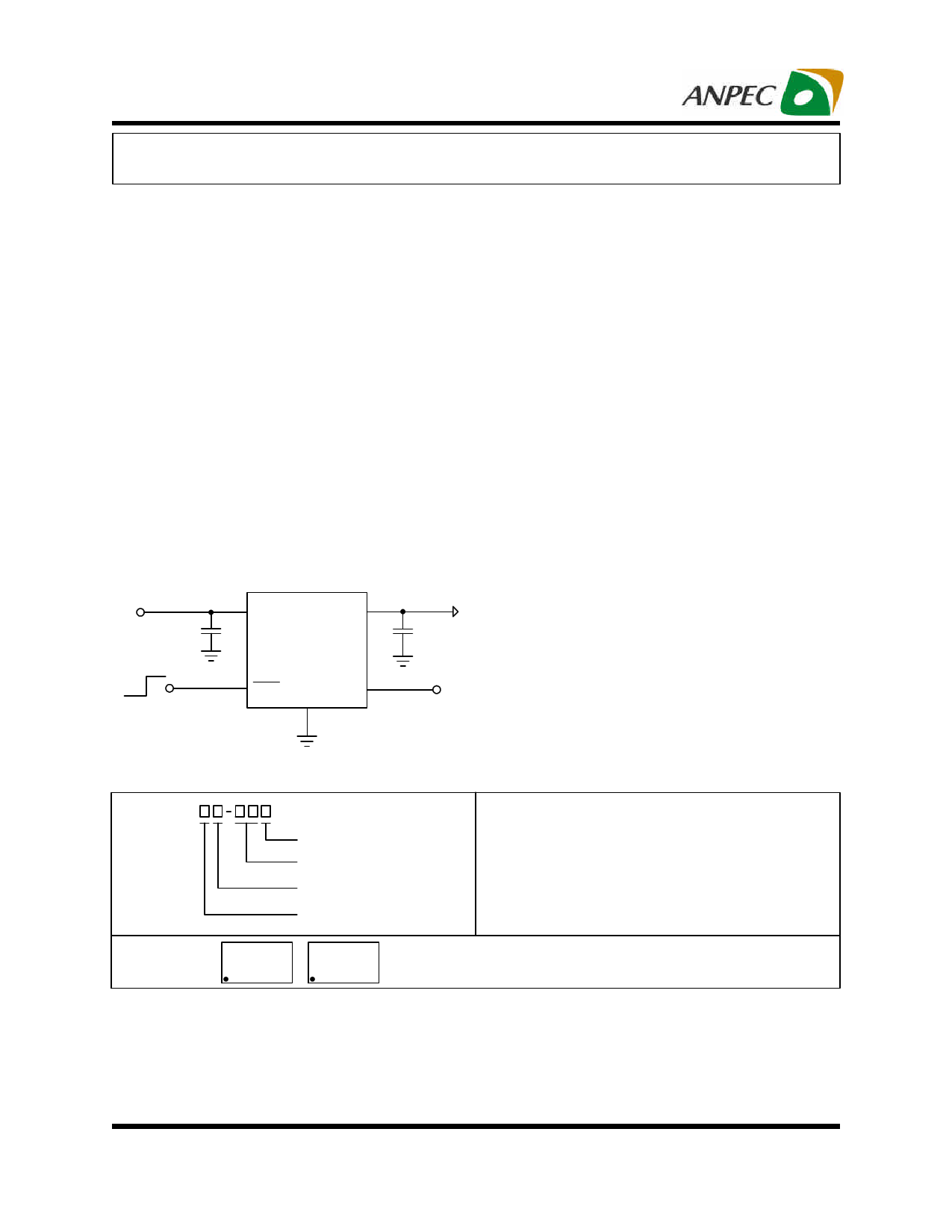
Simplified Application Circuit
VIN
C1
1µF
Adjustable mode
Full speed mode
VIN VOUT
APL5606/A
FSM
GND
VSE
T
VOUT
C2
2.2µF
Speed control
voltage (VSET)
The APL5606/A is a low quiescent current and low drop-
out linear regulator which is designed with a P-channel
pass MOSFET to power a DC fan and delivers output
current up to 600mA. In adjustable mode, the output
voltage follows the 1.6 times of the voltage on VSET pin to
dynamically adjust the DC fan speed; in full speed mode,
the internal P-channel MOSFET fully turns on to drive the
DC fan with maximum supply voltage for full speed
operation.The APL5606/A with low 140µA quiescent cur-
rent is ideal for battery-powered system appliances. It
is also stable with a low-ESR ceramic output capacitor (
2.2µF typical) to reduce total cost and to minimize the
PCB area required. The APL5606/A features current-limit
(with foldback current) and over-temperature protections
to protect the device against current over-loads and over-
temperature. The APL5606/A is available in a SOP-8
package.
Applications
• Notebook Fan Driver
• Motherboards
• PC Peripherals
• Battery-Powered System
Ordering and Marking Information
APL5606/A
Assembly Material
Handling Code
Temperature Range
Package Code
Package Code
K : SOP-8
Operating Ambient Temperature Range
I : -40 to 85 oC
Handling Code
TR : Tape & Reel
Assembly Material
L : Lead Free Device
G : Halogen and Lead Free Device
APL5606/A K : APL5606
XXXXX
APL5606A
XXXXX
XXXXX - Date Code
Note: ANPEC lead-free products contain molding compounds/die attach materials and 100% matte tin plate termination finish; which
are fully compliant with RoHS. ANPEC lead-free products meet or exceed the lead-free requirements of IPC/JEDEC J-STD-020D for
MSL classification at lead-free peak reflow temperature. ANPEC defines “Green” to mean lead-free (RoHS compliant) and halogen
free (Br or Cl does not exceed 900ppm by weight in homogeneous material and total of Br and Cl does not exceed 1500ppm by
weight).
ANPEC reserves the right to make changes to improve reliability or manufacturability without notice, and
advise customers to obtain the latest version of relevant information to verify before placing orders.
Copyright © ANPEC Electronics Corp.
Rev. A.4 - Dec., 2010
1
www.anpec.com.tw
1 page 
APL5606/A
Typical Operating Characteristics (Cont.)
V =5V,
IN
V =2V,
SET
V =3.2V,
OUT
CIN=1µF,
COUT=2.2µF,
unless
otherwise
specified.
Quiescent Current vs. Input Voltage
200
160
IOUT=0mA
120
80
40
0
012 3 456
Input Voltage, VIN (V)
Copyright © ANPEC Electronics Corp.
Rev. A.4 - Dec., 2010
5
www.anpec.com.tw
5 Page 
APL5606/A
Application Information
Input Capacitor
The APL5606/A requires proper input capacitors to sup-
ply surge current during stepping load transients to pre-
vent the input rail from dropping. Because the parasitic
inductor from the voltage sources or other bulk capaci-
tors to the VIN limits the slew rate of the surge current,
place the Input capacitors near VIN as close as possible.
The input capacitors should be larger than 0.82µF.
Output Capacitor
The APL5606/A needs a proper output capacitor to main-
tain circuit stability and to improve transient response
over-temperature and current. In order to insure the cir-
cuit stability, the proper output capacitor value should be
larger than 1µF. With X5R and X7R dielectrics, 2.2µF is
sufficient at all operating temperatures.
Operation Region and Power Dissipation
PCB Layout Consideration
Figure 1 illustrates the layout. Below is a checklist for
your layout:
1. Please place the input capacitors close to the VIN
2. Ceramic capacitors for load must be placed near the
load as close as possible
3. To place APL5606/A and output capacitors near the load
is good for performance.
4. Large current paths, the bold lines in figure 1, must
have wide tracks.
VIN
CIN
APL5606/A
VIN VSET
VSET
VFSM
FSM
VOUT
GND
VOUT
COUT
The APL5606/A maximum power dissipation depends
on the thermal resistance and temperature difference be-
tween the die junction and ambient air. The power dissi-
pation PD across the device is:
PD = (TJ − TA)
θJA
where (T -T ) is the temperature difference between the
JA
junction and ambient air. JA is the thermal resistance
between Junction and ambient air. Assuming the TA=25οC
and maximum TJ=150οC (typical thermal limit threshold),
the maximum power dissipation is calculated as:
P =(150-25)/80
D(max)
= 1.56 (W)
For normal operation, do not exceed the maximum junc-
tion temperature of TJ = 125οC. The calculated power
dissipation should be less than:
PD =(125-25)/80
= 1.25 (W)
Figure 1
Optimum performance can only be achieved when the
device is mounted on a PC board according to the SOP-8
Board Layout diagram.
For dissipating heat
GND
SOP-8
COUT
VIN CIN VOUT
GND
Figure 2
Recommanded Minimum Footprint
0.024
8765
1234
0.050 Unit : Inch
Copyright © ANPEC Electronics Corp.
Rev. A.4 - Dec., 2010
11
www.anpec.com.tw
11 Page | ||
| Páginas | Total 16 Páginas | |
| PDF Descargar | [ Datasheet APL5606A.PDF ] | |
Hoja de datos destacado
| Número de pieza | Descripción | Fabricantes |
| APL5606 | Low Dropout 600mA Linear Regulator | ANPEC |
| APL5606A | Low Dropout 600mA Linear Regulator | ANPEC |
| Número de pieza | Descripción | Fabricantes |
| SLA6805M | High Voltage 3 phase Motor Driver IC. |
Sanken |
| SDC1742 | 12- and 14-Bit Hybrid Synchro / Resolver-to-Digital Converters. |
Analog Devices |
|
DataSheet.es es una pagina web que funciona como un repositorio de manuales o hoja de datos de muchos de los productos más populares, |
| DataSheet.es | 2020 | Privacy Policy | Contacto | Buscar |