|
|
|
PDF NTP4804NG Data sheet ( Hoja de datos )
| Número de pieza | NTP4804NG | |
| Descripción | Power MOSFET ( Transistor ) | |
| Fabricantes | ON Semiconductor | |
| Logotipo | ||
Hay una vista previa y un enlace de descarga de NTP4804NG (archivo pdf) en la parte inferior de esta página. Total 6 Páginas | ||
|
No Preview Available !
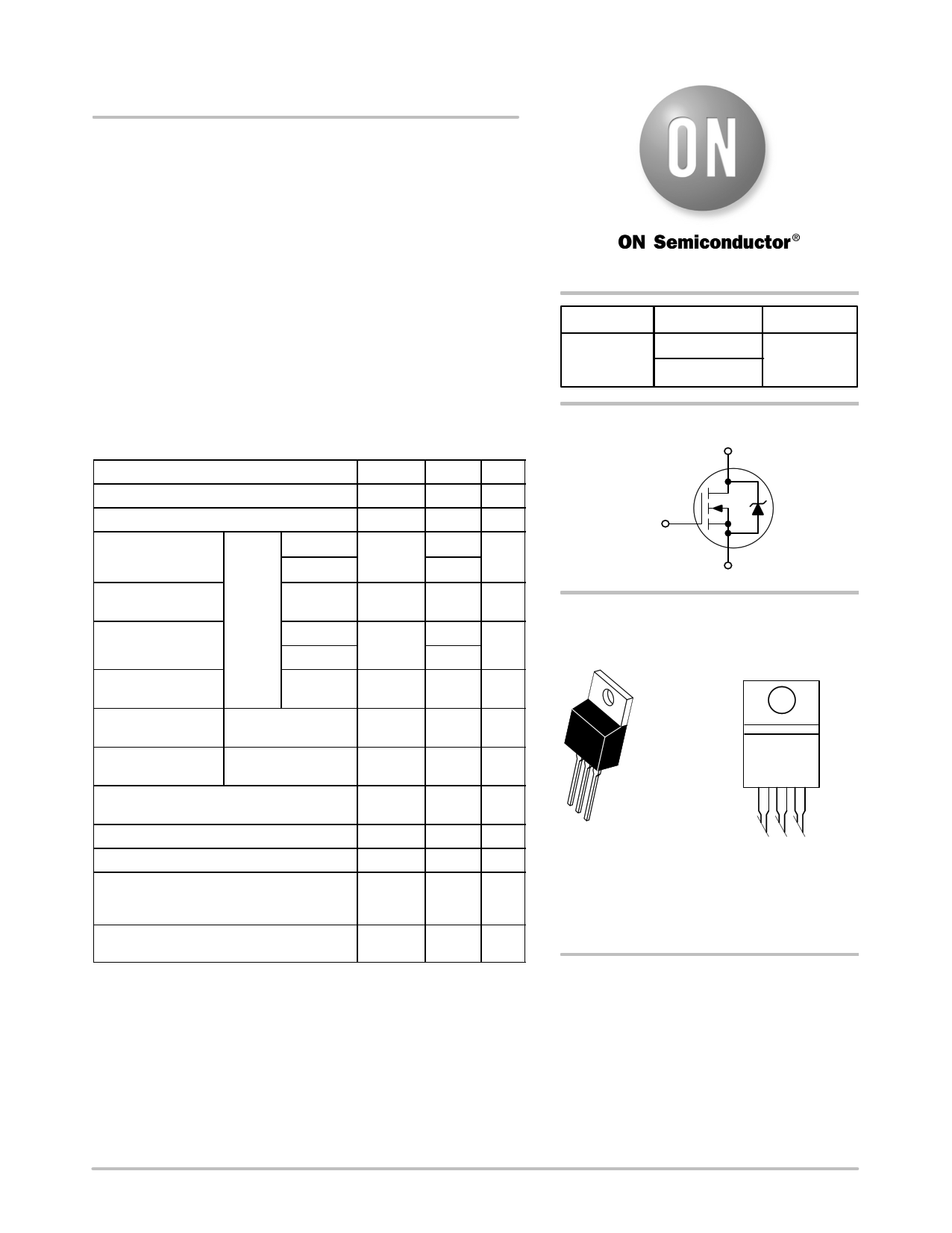
NTP4804N
Power MOSFET
30 V, 133 A, Single N−Channel, TO−220
Features
• Low RDS(on) to Minimize Conduction Losses
• Low Capacitance to Minimize Driver Losses
• Optimized Gate Charge to Minimize Switching Losses
• These are Pb−Free Devices*
Applications
• AC–DC Converters
• DC−DC Converters
• Low Side Switching
MAXIMUM RATINGS (TJ = 25°C unless otherwise stated)
Parameter
Symbol Value
Unit
Drain−to−Source Voltage
Gate−to−Source Voltage
Continuous Drain
(CNuortreen1t)RqJA
Power Dissipation
RqJA (Note 1)
Continuous Drain
Current RqJC
Steady
State
Power Dissipation
RqJC
TA = 25°C
TA = 85°C
TA = 25°C
TC = 25°C
TC = 85°C
TC = 25°C
VDSS
VGS
ID
PD
ID
PD
30 V
±20 V
21 A
13
3.0 W
133 A
85
120 W
Pulsed Drain
Current
Current Limited by
Package
TA = 25°C,
tp = 10 ms
TA = 25°C
IDM
IDmaxPkg
350
45
A
A
Operating Junction and Storage
Temperature
TJ, TSTG −55 to
+175
°C
Source Current (Body Diode)
Drain to Source DV/DT
IS
dV/dt
78 A
6 V/ns
Single Pulse Drain−to−Source Avalanche
Energy TJ = 25°C, VDD = 24 V, VGS = 10 V,
IL(pk) = 56 A, L = 0.3 mH, RG = 25 W
Lead Temperature for Soldering Purposes
(1/8” from case for 10 s)
EAS
TL
474 mJ
260 °C
*For additional information on our Pb−Free strategy and soldering details, please
download the ON Semiconductor Soldering and Mounting Techniques
Reference Manual, SOLDERRM/D.
http://onsemi.com
V(BR)DSS
30 V
RDS(on) MAX
4.0 mW @ 10 V
5.5 mW @ 4.5 V
ID MAX
133 A
N−Channel
D
G
4
S
MARKING DIAGRAM
& PIN ASSIGNMENT
4
Drain
12
3
TO−220AB
CASE 221A
STYLE 5
NTP4804NG
AYWW
1
Gate
2
Drain
3
Source
A = Assembly Location
Y = Year
WW = Work Week
G = Pb−Free Package
ORDERING INFORMATION
See detailed ordering and shipping information in the package
dimensions section on page 3 of this data sheet.
© Semiconductor Components Industries, LLC, 2009
March, 2009 − Rev. 0
1
Publication Order Number:
NTP4804N/D
1 page 
NTP4804N
TYPICAL CHARACTERISTICS
6000
5000
4000
3000
Ciss
VGS = 0 V
TJ = 25°C
10
5
QT
VDS
20
VGS
10
2000
1000
0
10
Crss
50
Vgs
Coss
5 10 15 20 25 30
Vds
GATE−TO−SOURCE OR DRAIN−TO−SOURCE VOLTAGE (V)
Figure 7. Capacitance Variation
1000
100
VDD = 15 V
ID = 15 A
VGS = 10 V
td(off)
tf
tr
td(on)
0
0
60
50
40
30
Qgs Qgd
ID = 30 A
TJ = 25°C
0
5 10 15 20 25 30
Qg, TOTAL GATE CHARGE (nC)
Figure 8. Gate−to−Source and
Drain−to−Source Voltage vs. Total Charge
VGS = 0 V
TJ = 25°C
10 20
10
1
1 10 100
RG, GATE RESISTANCE (W)
Figure 9. Resistive Switching Time Variation
vs. Gate Resistance
0
0.4
0.5
0.6
0.7 0.8
0.9 1.0
VSD, SOURCE−TO−DRAIN VOLTAGE (V)
Figure 10. Diode Forward Voltage vs. Current
http://onsemi.com
5
5 Page | ||
| Páginas | Total 6 Páginas | |
| PDF Descargar | [ Datasheet NTP4804NG.PDF ] | |
Hoja de datos destacado
| Número de pieza | Descripción | Fabricantes |
| NTP4804N | Power MOSFET ( Transistor ) | ON Semiconductor |
| NTP4804NG | Power MOSFET ( Transistor ) | ON Semiconductor |
| Número de pieza | Descripción | Fabricantes |
| SLA6805M | High Voltage 3 phase Motor Driver IC. |
Sanken |
| SDC1742 | 12- and 14-Bit Hybrid Synchro / Resolver-to-Digital Converters. |
Analog Devices |
|
DataSheet.es es una pagina web que funciona como un repositorio de manuales o hoja de datos de muchos de los productos más populares, |
| DataSheet.es | 2020 | Privacy Policy | Contacto | Buscar |