|
|
|
PDF OKDH-T-40-W12-001-C Data sheet ( Hoja de datos )
| Número de pieza | OKDH-T-40-W12-001-C | |
| Descripción | 40A Digital PoL DC-DC Converter | |
| Fabricantes | Murata | |
| Logotipo | ||
Hay una vista previa y un enlace de descarga de OKDH-T-40-W12-001-C (archivo pdf) en la parte inferior de esta página. Total 30 Páginas | ||
|
No Preview Available !
www.murata-ps.com
OKDx-T/40-W12-xxx-C
40A Digital PoL DC-DC Converter Series
PRELIMINARY
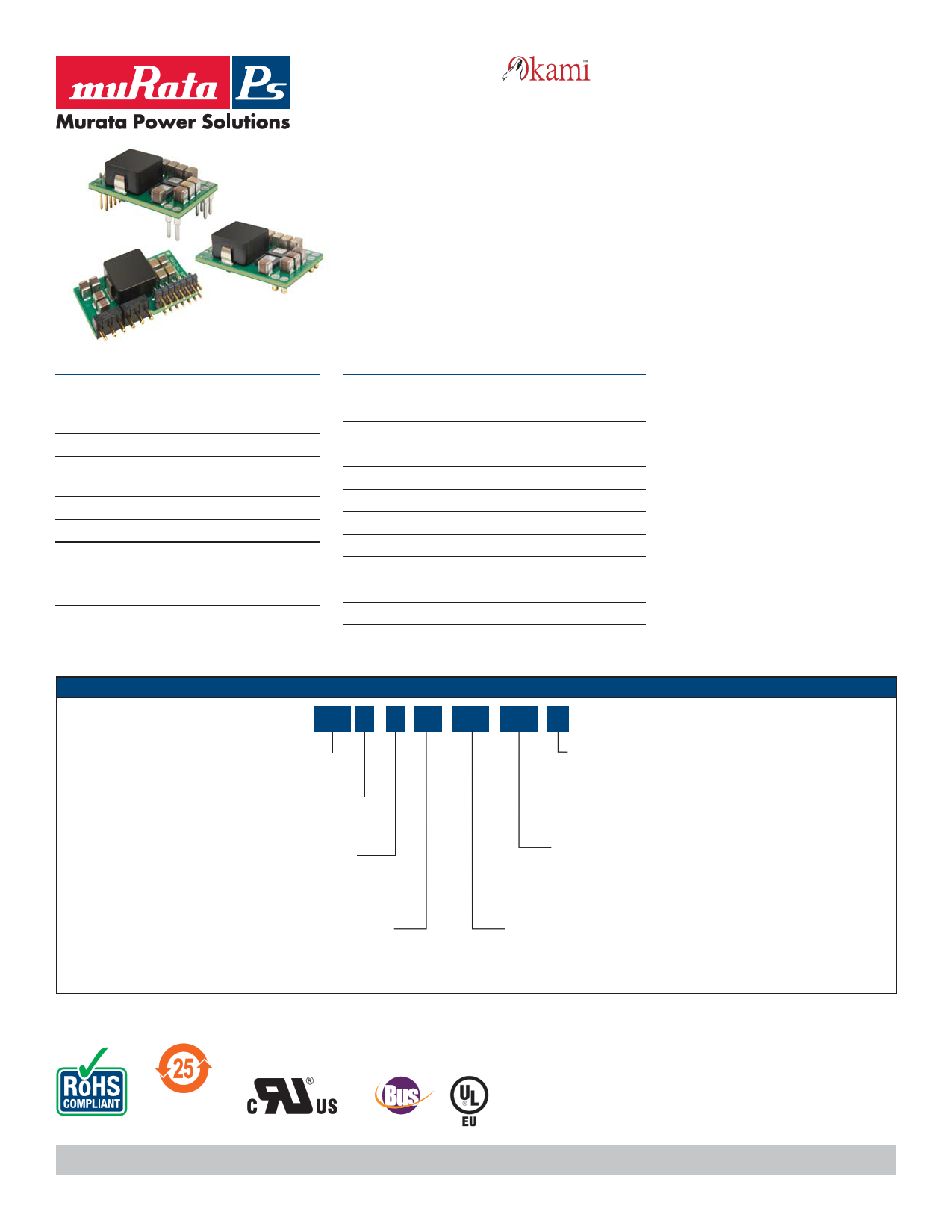
Typical units
FEATURES
Small package:
30.85 x 20.0 x 8.2 mm (1.215 x 0.787 x 0.323 in)
SIP: 33.0 x 7.6 x 18.1 mm (1.30 x 0.30 x 0.713 in)
0.6 V - 3.3 V output voltage range
High efficiency, typ. 97.2% at 5Vin, 3.3Vout half
load
Configuration and Monitoring via PMBus
Synchonization & phase spreading
Current sharing, Voltage Tracking & Voltage
margining
MTBF 14.2 Mh
PRODUCT OVERVIEW
Fully regulated
For narrow board pitch applications (15 mm/0.6 in)
Non-Linear Response for reduction of decoupling cap.
Input under voltage shutdown
Over temperature protection
Output short-circuit & Output over voltage protection
Remote control & Power Good
Voltage setting via pin-strap or PMBus
Configurable via Graphical User Interface
ISO 9001/14001 certified supplier
Highly automated manufacturing ensures quality
PART NUMBER STRUCTURE
OKD x - T / 40 - W12 - xxx - C
Digital Non-isolated PoL
Y = Surface Mount
H = Horizontal Mount Through-Hole
X = SIP
Trimmable Output
Voltage Range
0.6 - 3.3Vdc
RoHS Hazardous
Substance Compliance
C = RoHS-6 (does not claim EU RoHS exemption
7b – lead in solder)
Software Configuration Digits
(001 is positive turn-on logic)
Maximum Rated Output
Current in Amps
Input Voltage Range
4.5-14Vdc
For full details go to
www.murata-ps.com/rohs
www.murata-ps.com/support
PM
MDC_OKDx-T/40-W12-xxx-C.A01.D6 Page 1 of 40
1 page 
OKDx-T/40-W12-xxx-C
40A Digital PoL DC-DC Converter Series
Electrical Specifications, OKDY-T/40-W12-xxx-C and OKDH-T/40-W12-xxx-C
TP1 = -30 to +95°C, VIN = 4.5 to 14 V, VIN > VOUT + 1.0 V
Typical values given at: TP1 = +25 °C, VIN = 12.0 V, max IOUT, unless otherwise specified under Conditions.
Default configuration file, 190 10-CDA 102 0206/001.
External CIN = 470 μF/10 mΩ, COUT = 470 μF/10 mΩ. See Operating Information section for selection of capacitor types.
Sense pins are connected to the output pins.
PRELIMINARY
Characteristics
VI Input voltage rise time
Conditions
Monotonic
Min Typ Max Unit
2.4 V/ms
Output voltage without pin strap
Output voltage adjustment range
Output voltage adjustment including margining
Output voltage set-point resolution
Output voltage accuracy
Internal resistance +S/-S to VOUT/GND
VO
Line regulation
Load regulation; IO = 0 - 100%
VOac
Output ripple & noiseCO = 470 μF (minimum external
capacitance). See Note 11
See Note 17
Including line, load, temp.
See Note 14
Current sharing operation
See Note 15
VO = 0.6 V
VO = 1.0 V
VO = 1.8V
VO = 3.3 V
VO = 0.6 V
VO = 1.0 V
VO = 1.8V
VO = 3.3 V
VO = 0.6 V
VO = 1.0 V
VO = 1.8 V
VO = 3.3 V
1.2
0.60 3.3
0.54 3.63
±0.025
-1 1
V
V
V
% FS
%
-2 2 %
4.7 Ω
2
3
mV
3
3
2
2
mV
2
2
15
20
mVp-p
25
35
IO Output current
See Note 18
VO = 0.6 V
IS Static input current at max IO
VO = 1.0 V
VO = 1.8 V
VO = 3.3 V
Ilim Current limit threshold
VO = 0.6 V
Isc
Short circuit current
RMS, hiccup mode, See Note 3
VO = 1.0 V
VO = 1.8 V
VO = 3.3 V
0.001
42
2.45
3.80
6.49
11.58
10
9
9
7
40
52
A
A
A
A
VO = 0.6 V
50% of max IO
VO = 1.0 V
VO = 1.8 V
Efficiency
VO = 3.3 V
VO = 0.6 V
max IO
VO = 1.0 V
VO = 1.8 V
VO = 3.3 V
VO = 0.6 V
Pd Power dissipation at max IO
VO = 1.0 V
VO = 1.8 V
VO = 3.3 V
VO = 0.6 V
Pli
Input idling power
(no load)
Default configuration: Continues VO = 1.0 V
Conduction Mode, CCM
VO = 1.8 V
VO = 3.3 V
84.6
89.7
%
93.3
95.3
81.8
87.7
%
92.4
95.0
5.37
5.60
W
5.92
6.98
1.10
1.10
W
1.40
2.20
www.murata-ps.com/support
MDC_OKDx-T/40-W12-xxx-C.A01.D6 Page 5 of 40
5 Page 
Typical Characteristics
Output Voltage
Output Ripple & Noise, VO = 1.0 V
OKDx-T/40-W12-xxx-C
40A Digital PoL DC-DC Converter Series
PRELIMINARY
Output Ripple & Noise, VO = 3.3 V
Output voltage ripple at: TP1 = +25 °C, VI = 12Trace: output voltage (10 mV/div.).
V, CO = 470 μF/10 mΩ
Time scale: (2 μs/div.).
IO = 40 A
Output Ripple vs. Input Voltage
[mVpk-pk]
40
30
0.6 V
1.0 V
20
1.8 V
3.3 V
10
0
5 7 9 11 13 [V]
Output voltage ripple Vpk-pk at: TP1 = +25°C, CO = 470 μF/10 mΩ, IO = 40 A.
Output Ripple vs. External Capacitance
[mV]
40
30
20
10
0
0 1 2 3 4 5 [mF]
Output voltage ripple Vpk-pk at: TP1 = +25 °C, VI = 12 V, IO = 40 A.
Parallel coupling of capacitors with 470 μF/10 mΩ,
0.6 V
1.0 V
1.8 V
3.3 V
Output voltage ripple at: TP1 = +25 °C,
VI = 12 V, CO = 470 μF/10 mΩ
IO = 40 A
Output Ripple vs. Frequency
Trace: output voltage (10 mV/div.).
Time scale: (2 μs/div.).
[mVpk-pk]
100
80
0.6 V
60
1.0 V
40 1.8 V
3.3 V
20
0
200 250 300 350 400 450 500 550 600 [kHz]
Output voltage ripple Vpk-pk at: TP1 = +25°C, VI = 12 V, CO = 470 μF/10 mΩ,
IO = 40 A. Default configuration except changed frequency.
Load regulation, VO = 1.0 V
[V]
1.010
1.005
1.000
0.995
4.5 V
5.0 V
12 V
14 V
0.990
0
8 16 24 32 40 [A]
Load regulation at Vo = 1.0 V at: TP1 = +25 °C, CO = 470 μF/10 mΩ
www.murata-ps.com/support
MDC_OKDx-T/40-W12-xxx-C.A01.D6 Page 11 of 40
11 Page | ||
| Páginas | Total 30 Páginas | |
| PDF Descargar | [ Datasheet OKDH-T-40-W12-001-C.PDF ] | |
Hoja de datos destacado
| Número de pieza | Descripción | Fabricantes |
| OKDH-T-40-W12-001-C | 40A Digital PoL DC-DC Converter | Murata |
| Número de pieza | Descripción | Fabricantes |
| SLA6805M | High Voltage 3 phase Motor Driver IC. |
Sanken |
| SDC1742 | 12- and 14-Bit Hybrid Synchro / Resolver-to-Digital Converters. |
Analog Devices |
|
DataSheet.es es una pagina web que funciona como un repositorio de manuales o hoja de datos de muchos de los productos más populares, |
| DataSheet.es | 2020 | Privacy Policy | Contacto | Buscar |