|
|
|
PDF LTM4603HV Data sheet ( Hoja de datos )
| Número de pieza | LTM4603HV | |
| Descripción | DC/DC uModule | |
| Fabricantes | Linear Technology | |
| Logotipo | ||
Hay una vista previa y un enlace de descarga de LTM4603HV (archivo pdf) en la parte inferior de esta página. Total 26 Páginas | ||
|
No Preview Available !
Features
n Complete Switch Mode Power Supply
n Wide Input Voltage Range: 4.5V to 28V
n 6A DC Typical, 8A Peak Output Current
n 0.6V to 5V Output Voltage
n Output Voltage Tracking and Margining
n Remote Sensing for Precision Regulation
n Typical Operating Frequency: 1MHz
n PLL Frequency Synchronization
n 1.5% Regulation
n Current Foldback Protection (Disabled at Start-Up)
n Pin Compatible with the LTM4601/LTM4601HV/
LTM4603
n Ultrafast Transient Response
n Current Mode Control
n Up to 93% Efficiency at 5VIN, 3.3VOUT
n Programmable Soft-Start
n Output Overvoltage Protection
n RoHS Compliant Package with Gold Finish Pads (e4)
n Small Footprint, Low Profile (15mm × 15mm ×
2.82mm) Surface Mount LGA Package
Applications
n Telecom and Networking Equipment
n Servers
n Industrial Equipment
n Point of Load Regulation
LTM4603HV
6A, 28VIN DC/DC µModule
with PLL, Output Tracking
and Margining
Description
The LTM®4603HV is a complete 6A step-down switch mode
DC/DC power supply with onboard switching controller,
MOSFETs, inductor and all support components. The
µModuleTM is housed in a small surface mount 15mm ×
15mm × 2.82mm LGA package. Operating over an input
voltage range of 4.5 to 28V, the LTM4603HV supports
an output voltage range of 0.6V to 5V as well as output
voltage tracking and margining. The high efficiency design
delivers 6A continuous current (8A peak). Only bulk input
and output capacitors are needed to complete the design.
The low profile (2.82mm) and light weight (1.7g) package
easily mounts on the unused space on the back side of
PC boards for high density point of load regulation. The
µModule can be synchronized with an external clock for
reducing undesirable frequency harmonics and allows
PolyPhase® operation for high load currents.
A high switching frequency and adaptive on-time current
mode architecture deliver a very fast transient response
to line and load changes without sacrificing stability. An
onboard remote sense amplifier can be used to accurately
regulate an output voltage independent of load current.
L, LT, LTC, LTM, Linear Technology, the Linear logo, µModule and PolyPhase are registered
trademarks and LTpowerCAD is a trademark of Linear Technology Corporation. All other
trademarks are the property of their respective owners. Protected by U.S. Patents including
5481178, 5847554, 6580258, 6304066, 6476589, 6774611, 6677210.
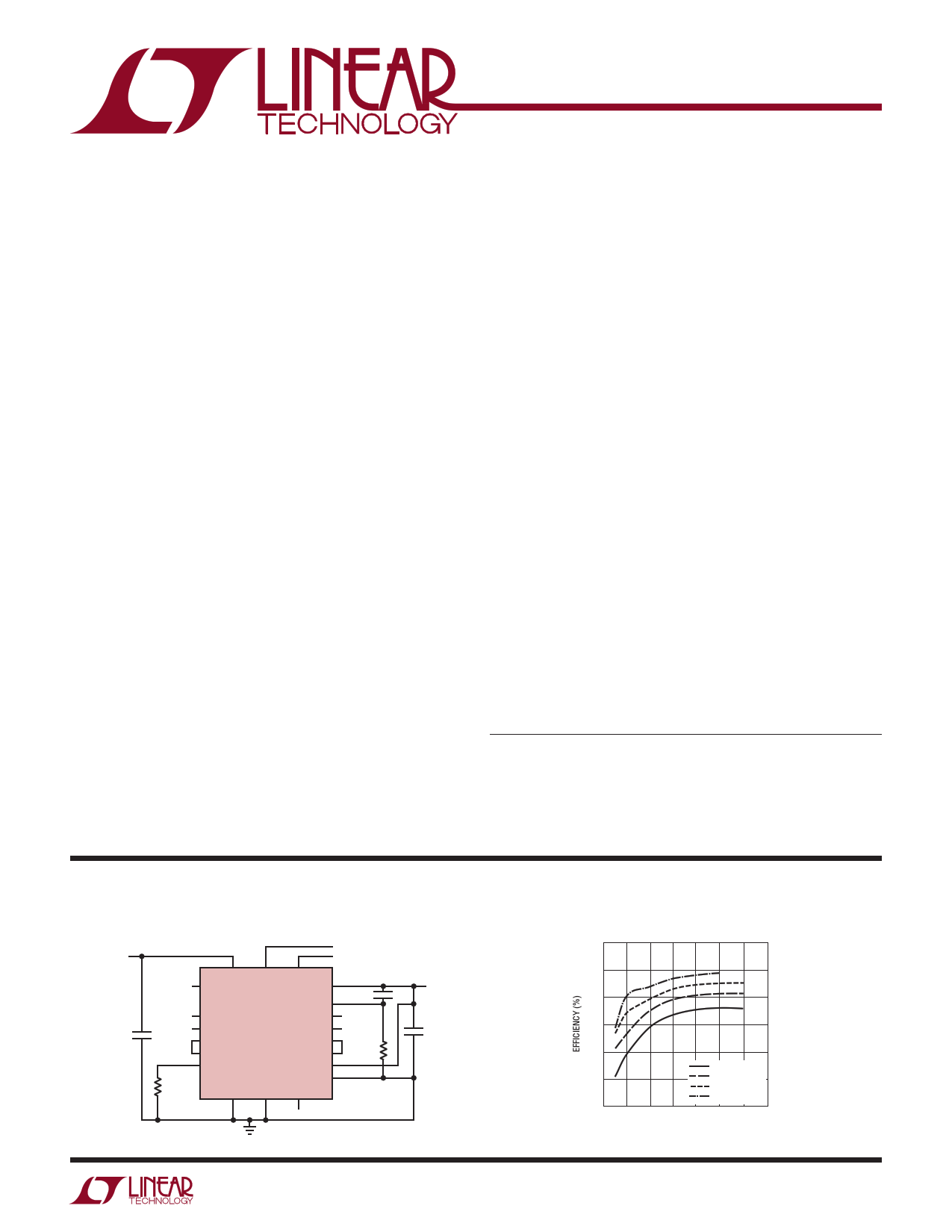
Typical Application
2.5V/6A with 4.5V to 28V Input µModule Regulator
VIN
4.5V TO 28V
CIN
CLOCK SYNC
TRACK/SS CONTROL
ON/OFF
R1
392k
VIN
PGOOD
PLLIN TRACK/SS
VOUT
VFB
RUN MARG0
COMP
INTVCC
LTM4603HV MARG1
VOUT_LCL
DRVCC
MPGM
DIFFVOUT
VOSNS+
VOSNS–
SGND PGND fSET
100pF
MARGIN
CONTROL
RSET
19.1k
VOUT
2.5V
6A
COUT
5% MARGIN
4603HV TA01a
Efficiency vs Load Current with 24VIN
100
90
80
70
60
50
40
01
24VIN, 1.8VOUT
24VIN, 2.5VOUT
24VIN, 3.3VOUT
24VIN, 5VOUT
2 34 5 6 7
LOAD CURRENT (A)
4603HV TA01b
For more information www.linear.com/LTM4603HV
4603hvfa
1
1 page 
LTM4603HV
Typical Performance Characteristics (See Figure 20 for all curves)
Efficiency vs Load Current
with 5VIN
100
90
80
70
60
5VIN, 0.6VOUT
5VIN, 1.2VOUT
5VIN, 1.5VOUT
50 5VIN, 1.8VOUT
5VIN, 2.5VOUT
40 5VIN, 3.3VOUT
01 2 34 5 6 7
LOAD CURRENT (A)
4603HV G01
Efficiency vs Load Current
with 12VIN
100
90
80
70
60
12VIN, 1.2VOUT
12VIN, 1.5VOUT
12VIN, 1.8VOUT
50 12VIN, 2.5VOUT
12VIN, 3.3VOUT
40 12VIN, 5VOUT
01 2 34 5 6 7
LOAD CURRENT (A)
4603HV G02
Efficiency vs Load Current
with 24VIN
100
90
80
70
60
50
40
01
24VIN, 1.8VOUT
24VIN, 2.5VOUT
24VIN, 3.3VOUT
24VIN, 5VOUT
2 34 5 6 7
LOAD CURRENT (A)
4603HV G03
1.2V Transient Response
1.5V Transient Response
1.8V Transient Response
LOAD STEP
1A/DIV
LOAD STEP
1A/DIV
LOAD STEP
1A/DIV
VOUT
50mV/DIV
VOUT
50mV/DIV
VOUT
50mV/DIV
25µs/DIV
1.2V AT 3A/µs LOAD STEP
COUT: 1x 22µF, 6.3V CERAMIC
1x 330µF, 4V SANYO POSCAP
4603HV G04
25µs/DIV
1.5V AT 3A/µs LOAD STEP
COUT: 1x 22µF, 6.3V CERAMIC
1x 330µF, 4V SANYO POSCAP
4603HV G05
25µs/DIV
1.8V AT 3A/µs LOAD STEP
COUT: 1x 22µF, 6.3V CERAMIC
1x 330µF, 4V SANYO POSCAP
4603HV G06
2.5V Transient Response
LOAD STEP
1A/DIV
VOUT
50mV/DIV
25µs/DIV
2.5V AT 3A/µs LOAD STEP
COUT: 1x 22µF, 6.3V CERAMIC
1x 330µF, 4V SANYO POSCAP
4603HV G07
3.3V Transient Response
LOAD STEP
1A/DIV
VOUT
50mV/DIV
25µs/DIV
3.3V AT 3A/µs LOAD STEP
COUT: 1x 22µF, 6.3V CERAMIC
1x 330µF, 4V SANYO POSCAP
4603HV G08
For more information www.linear.com/LTM4603HV
4603hvfa
5
5 Page 
LTM4603HV
Applications Information
The typical LTM4603HV application circuit is shown in
Figure 20. External component selection is primarily
determined by the maximum load current and output
voltage. Refer to Table 2 for specific external capacitor
requirements for a particular application.
VIN to VOUT Step-Down Ratios
There are restrictions in the maximum VIN and VOUT step
down ratio that can be achieved for a given input voltage.
These constraints are shown in the Typical Performance
Characteristics curves labeled VIN to VOUT Step-Down
Ratio. Note that additional thermal derating may apply. See
the Thermal Considerations and Output Current Derating
section of this data sheet.
Output Voltage Programming and Margining
The PWM controller has an internal 0.6V reference voltage.
As shown in the Block Diagram, a 1M and a 60.4k 0.5%
internal feedback resistor connects VOUT and VFB pins
together. The VOUT_LCL pin is connected between the 1M
and the 60.4k resistor. The 1M resistor is used to protect
against an output overvoltage condition if the VOUT_LCL
pin is not connected to the output, or if the remote sense
amplifier output is not connected to VOUT_LCL. The output
voltage will default to 0.6V. Adding a resistor RSET from
the VFB pin to SGND pin programs the output voltage:
VOUT
=
0.6V
60.4k +RSET
RSET
Table 1. RSET Standard 1% Resistor Values vs VOUT
(RkSΩET) Open 60.4 40.2 30.1 25.5 19.1 13.3
V(OVU)T 0.6 1.2 1.5 1.8 2 2.5 3.3
8.25
5
The MPGM pin programs a current that when multiplied
by an internal 10k resistor sets up the 0.6V reference ±
offset for margining. A 1.18V reference divided by the
RPGM resistor on the MPGM pin programs the current.
Calculate VOUT(MARGIN):
VOUT(MARGIN)
=
%VOUT
100
• VOUT
where %VOUT is the percentage of VOUT you want to
margin, and VOUT(MARGIN) is the margin quantity in volts:
RPGM
=
VOUT
0.6V
•
1.18V
VOUT(MARGIN)
• 10k
where RPGM is the resistor value to place on the MPGM
pin to ground.
The margining voltage, VOUT(MARGIN), will be added or
subtracted from the nominal output voltage as determined
by the state of the MARG0 and MARG1 pins. See the truth
table below:
MARG1
LOW
LOW
HIGH
HIGH
MARG0
LOW
HIGH
LOW
HIGH
MODE
NO MARGIN
MARGIN UP
MARGIN DOWN
NO MARGIN
Input Capacitors
LTM4603HV module should be connected to a low AC
impedance DC source. Input capacitors are required to
be placed adjacent to the module. In Figure 20, the 10µF
ceramic input capacitors are selected for their ability to
handle the large RMS current into the converter. An input
bulk capacitor of 100µF is optional. This 100µF capacitor is
only needed if the input source impedance is compromised
by long inductive leads or traces.
For a buck converter, the switching duty-cycle can be
estimated as:
D
=
VOUT
VIN
Without considering the inductor ripple current, the RMS
current of the input capacitor can be estimated as:
ICIN(RMS)
=
IOUT(MAX )
η%
•
D • (1−D)
In the above equation, η% is the estimated efficiency of
the power module. CIN can be a switcher-rated electrolytic
aluminum capacitor, OS-CON capacitor or high value ce-
ramic capacitor. Note the capacitor ripple current ratings
For more information www.linear.com/LTM4603HV
4603hvfa
11
11 Page | ||
| Páginas | Total 26 Páginas | |
| PDF Descargar | [ Datasheet LTM4603HV.PDF ] | |
Hoja de datos destacado
| Número de pieza | Descripción | Fabricantes |
| LTM4603HV | DC/DC uModule | Linear Technology |
| Número de pieza | Descripción | Fabricantes |
| SLA6805M | High Voltage 3 phase Motor Driver IC. |
Sanken |
| SDC1742 | 12- and 14-Bit Hybrid Synchro / Resolver-to-Digital Converters. |
Analog Devices |
|
DataSheet.es es una pagina web que funciona como un repositorio de manuales o hoja de datos de muchos de los productos más populares, |
| DataSheet.es | 2020 | Privacy Policy | Contacto | Buscar |