|
|
|
PDF U2400B Data sheet ( Hoja de datos )
| Número de pieza | U2400B | |
| Descripción | Charging of Batteries | |
| Fabricantes | TEMIC | |
| Logotipo | ||
Hay una vista previa y un enlace de descarga de U2400B (archivo pdf) en la parte inferior de esta página. Total 15 Páginas | ||
|
No Preview Available !
U2400B
Charging of Batteries with Automatic Pre-Discharge
Description
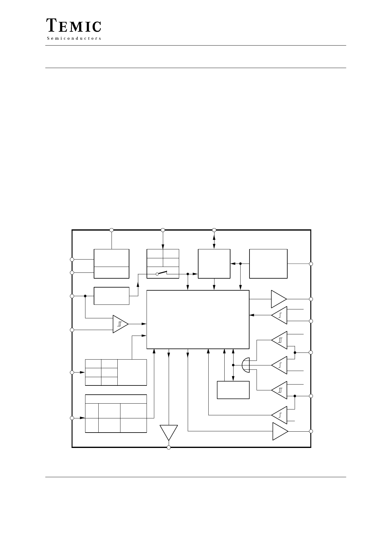
The monolithic integrated circuit, U2400B, is a bipolar
circuit, designed for automatic recharging of NiCd/
NiMH batteries. It has controlled and defined charging
characteristics for various charging sequences with
*subsequent trickle charge operation. The long life
*Memory Effect of the recharging cell remains intact.
Features
D Three time selections:
0.5 h, 1 h or 12 h with subsequent trickle charge
operation
D Battery temperature and contact monitoring
D Charging interrupt for overvoltage or excessive
temperature
D Automatic pre-discharge possible
D Separate charge- and discharge outputs
D Pulse-width modulation facility of charge- and
discharge current for matching to transformer or
battery data
D Timer clock via mains or internal oscillator
D Reference voltage source
D LED-status output for mode indication
Case: DIP16, SO16L
8 14
16
0.5 Hz
94 9375
11 Mains supply
7
Reference
Open Ref
on off
Test
logic
Mains
synchronization
1
3 200 Hz
Oscillator
–
2+
Control unit
PWM
Time
Status Discharge Reset
13
Ref 12 h
GND 1 h
Charge
time
selection
Open 0.5 h
Failure – charge mode
II Continue Alternating
15 Ref charging red / green
I Stop
Red
Open charging indicator
Status
display
output
9
Charge
Start
Stop
Charge
output 12
Discharge
stop
0.53 V
+
–6
0.53 V
+
–
Sensor
monitoring
5
+
– 2.95 V
Event
counter
Vmax
0.53 V
–
+4
Battery
contact monitoring
–
+ 0.18 V
10
Discharge
output
Figure 1. Block diagram
TELEFUNKEN Semiconductors
Rev. A2, 21-Nov-96
1 (15)
1 page 
U2400B
If a DC voltage in the range of 0.9 to 2.1 V is supplied to
comparator positive input (Pin 2), the discharge and
charge outputs are deactivated as soon as the oscillator’s
saw-tooth voltage (Pin 3) exceeds the DC voltage at Pin 2
(figures 9, 10 and 11). This pulse-width modulation
*effects the active discharge and charge output in each
mode discharge, charge or trickle charge. This offers
the possibility of matching the r.m.s. current to various
battery capacities by means of a switchable voltage
divider.
Pin 14 must be connected to reference voltage Pin 7, if
the internal clock signals are derived from the mains
synchronization input Pin 1 with simultaneous pulse-
width modulation. The oscillator can then be used
deviating from 200 Hz.
As soon as a battery is removed, the red LED is active
(= no contact). A total pause of approximately 2 seconds
must be given between removing the charged battery and
inserting a new battery to inform the IC that the inserted
battery is to be charged.
mA
I9
10
0
red
No battery contact
mA
I9 green
0
–10
800 ms
green
Charge
200 ms
internal 7
3V
red
9 O9 TLHR 5400
green
mA
I9
10
0
red
mA
I9 0
–10
TLHG 5400
mA
I9
0
800 ms
red Discharge
200 ms
green
Trickle charge
Stand – by
94 9379
mA
I9
10
0
red
mA
I9 10
0
–10
green
200 ms
red
green
200 ms
t
Figure 5. Status display output
Failure function I
Failure with
charge stop
Failure function II
Expired charge
time with
interruption
TELEFUNKEN Semiconductors
Rev. A2, 21-Nov-96
5 (15)
5 Page 
U2400B
Applications
Quick charge for NiCd-batteries with PWM method
Figure 15 describe the current regulations with PWM.
Mean value of the charge current for the battery which is
created across power transistor T2 is so dimensioned that
it is independent of supply and battery voltage. For the
purpose of regulation, load current is obtained via resistor
WR20 = 0.2 , whose voltage drop serves as actual value for
the operation amplifier. It is however recommended to
use PNP-differential input stage due to its relatively low
loss of power across the shunt resistance (P = 0.2 W, @
200 mV with 1 A charge current).
GND is the negative supply for operational amplifier
whereas the reference point for other components of the
IC is different i.e., positive shunt drop voltage. Current set
point is given across the voltage divider R15/P1 whereas
the actual value across R18 with a common point, the
resistance R20.
The output voltage of operational amplifier delivers the
voltage for PWM-control at Pin 2. Current regulation acts
only on charge current, whereas discharge current is spe-
cified by R14.
Maximum and minimum voltage adjustment for variety
of cells (batteries) can be calculated with R4/R2 and
R5/R3 ratios.
94 9388
0.5 h
12 h
1h
R9
16 15 14 13 12 11 10
9
Mode
Time Charge GND Discharge Status
U2400B
Sync PWM Osc Vmax Temp Vmin VRef +VS
12345678
R13
BD442
T2
D3 BYT77
Peak
R11 current
limitation
+12 V
R15
R19
C7
D2
+ LM358 R16
–
C6
R18
P1
Charge current set point
WR1 = 390 k
R2, R3 = see table 1, under figure 16
WR4, R5, R16, R18, R19 = 100 k
WR6 = 30 k
WR7, R8 = 270
D Charge current regulation
D Automatic pre-discharge
D Charge time: 0.5 h, 1 h, 12 h
R1
C2 C4
R4 R17
R5
R10
C5 C3 C1
R2 R6 R3
R12
T1
BD441
NTC Sensor
WR(25) =10 k
B value =3474
WR20 0.2
red
TLHR 5400
WR9, R10 = 180
WR12, R13, R15 = 10 k
WR17 = 1.5 k
WR20 = 0.2
P1 = 1 kW
R7 R8
green
TLHG 5400
mC1, C7 = 100 F
C2 = 15 nF
mC3 = 10 F
mC4, C5, C6 = 0.33 F
D2 = IN4148
GND
Figure 15.
D Temperature monitoring
D Status indication
TELEFUNKEN Semiconductors
Rev. A2, 21-Nov-96
11 (15)
11 Page | ||
| Páginas | Total 15 Páginas | |
| PDF Descargar | [ Datasheet U2400B.PDF ] | |
Hoja de datos destacado
| Número de pieza | Descripción | Fabricantes |
| U2400B | Charging of Batteries with Automatic Pre-Discharge | Vishay Telefunken |
| U2400B | Charging of Batteries | TEMIC |
| Número de pieza | Descripción | Fabricantes |
| SLA6805M | High Voltage 3 phase Motor Driver IC. |
Sanken |
| SDC1742 | 12- and 14-Bit Hybrid Synchro / Resolver-to-Digital Converters. |
Analog Devices |
|
DataSheet.es es una pagina web que funciona como un repositorio de manuales o hoja de datos de muchos de los productos más populares, |
| DataSheet.es | 2020 | Privacy Policy | Contacto | Buscar |