|
|
|
PDF FA5553 Data sheet ( Hoja de datos )
| Número de pieza | FA5553 | |
| Descripción | PWM Control Power Supply IC | |
| Fabricantes | Fuji | |
| Logotipo | ||
Hay una vista previa y un enlace de descarga de FA5553 (archivo pdf) en la parte inferior de esta página. Total 6 Páginas | ||
|
No Preview Available !
FA5553/5547 Series of PWM Control
Power Supply ICs with Multi-functionality
and Low Standby Power
Masanari Fujii
Hiroshi Maruyama
Kokou Boku
1. Introduction
In recent years, global environmental warming has
come to be addressed as a worldwide problem and ener-
gy savings has become critical for all electric products.
In particular, televisions, audio components, notebook
computers, printers and other such peripheral devices
that are often continuously plugged into an electri-
cal outlet remain in their standby state for a longer
duration of time than their actual time of usage, and
therefore functions for reducing the power consump-
tion during standby have become essential. Requests
for lower standby power consumption in power supply
units have also intensified year after year.
In response to these requests, Fuji Electric has
already developed a series of control ICs for use in
switching mode power supply units to convert commer-
cial AC power (100 V or 240 V) to a DC power supply.
Recently, Fuji Electric has developed the FA5553 / 5547
series of 8-pin current mode PWM (pulse width
modulation) control power supply ICs which feature
enhanced low standby power performance and added
protection functions suitable for various products. An
overview of this new product series is presented below.
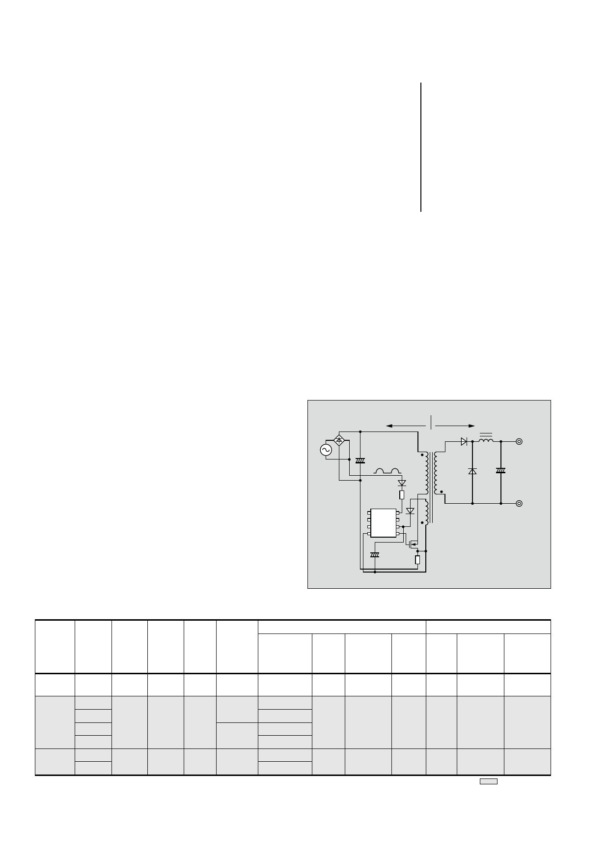
2. Product Overview
Fuji Electric has developed a series of AC-DC
power supply ICs for driving externally attached power
MOSFETs fabricated using a 30 V CMOS (comple-
mentary metal-oxide-semiconductor) process, and this
newly developed IC series is listed in Table 1. This IC
series is used as a PWM IC on the primary side in the
conceptual diagram of a switching mode power supply
shown in Fig. 1.
2.1 Characteristics
As indicated in Table 1 each unit type is provided
Fig.1 Conceptual diagram of switching mode power supply
AC power
supply
Primary side Secondary side
+
C1 Half-wave
RVH
PWM IC
LAT VH
FB (NC)
IS VCC
GND OUT
+ MOS
C2 gate
signal
RS
Main
winding
Auxiliary
winding
Secondary side
Output voltage /
current
+
Table 1 Characteristics of PWM IC series for low standby power
Series
Model
Power
Package
supply
configu-
ration
Input Operating
range frequency
Overload
Protection function
Low standby power function
Over-
voltage
Latch by
an external
signal
(overheat)
Brown-
out
Startup
circuit
Min. operating
frequency
during standby
Overload
line com-
pensation
loss
FA5528 FA5528
FA5553
FA5547
FA5553
FA5554
FA5566
FA5567
FA5546
FA5547
SOP/
DIP8
SOP/
DIP8
SOP/
DIP8
Flyback
10 to
26 V
Flyback
10 to
26 V
Flyback
10 to
26 V
60 kHz Timer latch Latch
60 kHz
100 kHz
60 kHz
Auto-restart
Timer latch
Auto-restart
Timer latch
Auto-restart
Timer latch
Latch
Latch
Yes
Yes
Yes
No Yes 1.1 kHz < 70 mW
No Yes 0.35 kHz < 5 mW
Yes Yes 0.5 kHz < 5 mW
: New product
68 Vol. 54 No. 2 FUJI ELECTRIC REVIEW
1 page 
Fig.10 Power supply circuit diagram
3.15 A 250 V
L F001 L001
N
FG
C001
0.33 F
R001
1 MΩ
R002
1 MΩ
L002
D050
~+
~-
C051
120
F
+
400 V
C006
C053 3.3 F
R053
T051
2
R051
FLY2
100 kΩ
10 Ω
D052
1
FLY1
D107
R107
0Ω
Q050
2SK3687
C050
100 pF
R102
360 Ω
R056-1
23.7 Ω
R056
0.68 Ω
R125
13 kΩ
RT100
TTC
104
D070
R006
4.7 kΩ
87 6
IC100 FA5553
12 3
+ C054
22 F
5 R127
22 kΩ
4
C115
1 F R126
20 kΩ
C116
0.47 F
C120
22 nF
R056 D051
6.8 Ω
C056
1F
R112
22 kΩ
R122
1 kΩ
PC300
R124
75 kΩ
R123
75 kΩ
L051
3
10
R200 C200
47 Ω 200 pF
D200
YG862C15
+
C204
470 F
C205 +
470 F
(+VOUT)
GND
PC300
9817
817A
R400
470 Ω
R405
10 kΩ
R401
33 kΩ
C400
0.1 F
R408
10 kΩ
C401
IC400
K1A
431A
R402
4.7 kΩ
Fig.11 Relationship between load current and operating fre-
quency
70
60
264 V AC
50
40
100 V AC
30
20
10
0 0 0.5 1.0
Load current (A)
1.5
Fig.12 Relationship between input voltage and input power for
unloaded output
0.20
0.18
0.16
0.14
0.12
0.10
0.08
0.06
0.04
0.02
0
60
120 180 240
Input voltage (VAC)
300
small number of components.
4. Postscript
A power supply IC that supports low standby
power and that enables various required protection
functions to be configured with a small number of
components has been described. In this field, requests
for lower power consumption are expected to intensify
in the future, and Fuji Electric intends to continue to
enhance functionality and reduce the number of com-
ponents to develop easy-to-use products.
72 Vol. 54 No. 2 FUJI ELECTRIC REVIEW
5 Page | ||
| Páginas | Total 6 Páginas | |
| PDF Descargar | [ Datasheet FA5553.PDF ] | |
Hoja de datos destacado
| Número de pieza | Descripción | Fabricantes |
| FA5550 | Switching Power Supply Control IC | Fuji |
| FA5551 | Switching Power Supply Control IC | Fuji |
| FA5553 | PWM Control Power Supply IC | Fuji |
| Número de pieza | Descripción | Fabricantes |
| SLA6805M | High Voltage 3 phase Motor Driver IC. |
Sanken |
| SDC1742 | 12- and 14-Bit Hybrid Synchro / Resolver-to-Digital Converters. |
Analog Devices |
|
DataSheet.es es una pagina web que funciona como un repositorio de manuales o hoja de datos de muchos de los productos más populares, |
| DataSheet.es | 2020 | Privacy Policy | Contacto | Buscar |