|
|
|
PDF IRG7SC28UPbF Data sheet ( Hoja de datos )
| Número de pieza | IRG7SC28UPbF | |
| Descripción | PDP Trench IGBT | |
| Fabricantes | International Rectifier | |
| Logotipo | ||
Hay una vista previa y un enlace de descarga de IRG7SC28UPbF (archivo pdf) en la parte inferior de esta página. Total 8 Páginas | ||
|
No Preview Available !
PD - 97569A
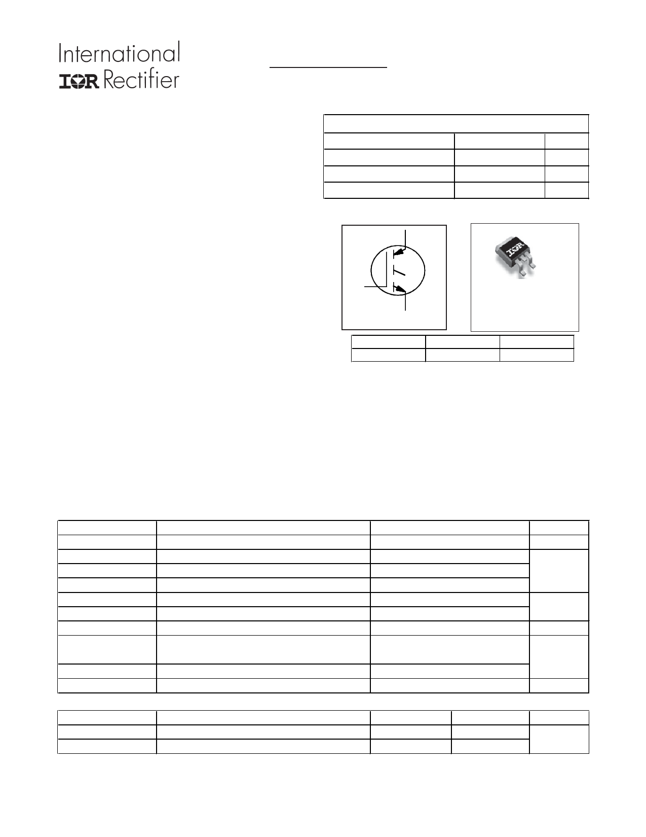
PDP TRENCH IGBT
IRG7SC28UPbF
Features
l Advanced Trench IGBT Technology
l Optimized for Sustain and Energy Recovery
circuits in PDP applications
l Low VCE(on) and Energy per Pulse (EPULSETM)
for improved panel efficiency
l High repetitive peak current capability
l Lead Free package
Key Parameters
VCE min
600
cVCE(ON) typ. @ IC = 40A
IRP max @ TC= 25°C
TJ max
1.70
225
150
CC
V
V
A
°C
G
E
n-channel
G
Gate
CE
G
D2Pak
IRG7SC28UPbF
C
Collector
E
Emitter
Description
This IGBT is specifically designed for applications in Plasma Display Panels. This device utilizes advanced
trench IGBT technology to achieve low VCE(on) and low EPULSETM rating per silicon area which improve panel
efficiency. Additional features are 150°C operating junction temperature and high repetitive peak current
capability. These features combine to make this IGBT a highly efficient, robust and reliable device for PDP
applications.
Absolute Maximum Ratings
Parameter
VGE
IC @ TC = 25°C
IC @ TC = 100°C
IRP @ TC = 25°C
PD @TC = 25°C
PD @TC = 100°C
Gate-to-Emitter Voltage
Continuous Collector Current, VGE @ 15V
Continuous Collector, VGE @ 15V
cRepetitive Peak Current
Power Dissipation
Power Dissipation
Linear Derating Factor
TJ
TSTG
Operating Junction and
Storage Temperature Range
Soldering Temperature for 10 seconds
Mounting Torque, 6-32 or M3 Screw
Thermal Resistance
Parameter
dRθJC Junction-to-Case
dRθJA Junction-to-Ambient (PCB Mount)
Max.
±30
60
30
225
171
68
1.37
-40 to + 150
300
x x10lb in (1.1N m)
Typ.
–––
–––
Max.
0.73
40
Units
V
A
W
W/°C
°C
N
Units
°C/W
www.irf.com
1
07/11/11
1 page 
IRG7SC28UPbF
100000
10000
1000
VGS = 0V, f = 1 MHZ
Cies = C ge + Cgd, C ce SHORTED
Cres = Cgc
Coes = Cce + Cgc
Cies
16
IC = 40A
14
12 VCES = 120V
10
VCES = 300V
VCES = 400V
8
6
100
Coes
Cres
10
0
100 200 300 400 500
VCE, Collector-toEmitter-Voltage(V)
Fig 13. Typical Capacitance vs. Collector-to-Emitter Voltage
4
2
0
0 10 20 30 40 50 60 70 80
Q G, Total Gate Charge (nC)
Fig 14. Typical Gate Charge vs. Gate-to-Emitter Voltage
6000
5000
4000
EOFF
3000
2000
1000
EON
0
0 10 20 30 40 50 60 70 80 90
IC (A)
Fig. 15 - Typ. Energy Loss vs. IC
TJ = 150°C; L = 250μH; VCE = 400V, RG = 22Ω; VGE = 15V
1
D = 0.50
0.20
0.1 0.10
0.01
0.05
0.02
0.01
τJ τJ
τ1 τ1
R1R1
R2R2
τ2 τ2
R3R3
τ3 τ3
R4R4
τCτ
Ri (°C/W)
0.01049
0.08396
τi (sec)
0.000003
0.000068
τ4τ4 0.36433 0.000904
0.001
1E-006
SINGLE PULSE
( THERMAL RESPONSE )
CiC= iτi/Ri/iRi
1E-005
0.0001
0.001
0.26987 0.008034
Notes:
1. Duty Factor D = t1/t2
2. Peak Tj = P dm x Zthjc + Tc
0.01
0.1
t1 , Rectangular Pulse Duration (sec)
Fig 16. Maximum Effective Transient Thermal Impedance, Junction-to-Case
www.irf.com
5
5 Page | ||
| Páginas | Total 8 Páginas | |
| PDF Descargar | [ Datasheet IRG7SC28UPbF.PDF ] | |
Hoja de datos destacado
| Número de pieza | Descripción | Fabricantes |
| IRG7SC28UPbF | PDP Trench IGBT | International Rectifier |
| Número de pieza | Descripción | Fabricantes |
| SLA6805M | High Voltage 3 phase Motor Driver IC. |
Sanken |
| SDC1742 | 12- and 14-Bit Hybrid Synchro / Resolver-to-Digital Converters. |
Analog Devices |
|
DataSheet.es es una pagina web que funciona como un repositorio de manuales o hoja de datos de muchos de los productos más populares, |
| DataSheet.es | 2020 | Privacy Policy | Contacto | Buscar |