|
|
|
PDF DMP4025LK3 Data sheet ( Hoja de datos )
| Número de pieza | DMP4025LK3 | |
| Descripción | 40V P-CHANNEL ENHANCEMENT MODE MOSFET | |
| Fabricantes | Diodes | |
| Logotipo | ||
Hay una vista previa y un enlace de descarga de DMP4025LK3 (archivo pdf) en la parte inferior de esta página. Total 8 Páginas | ||
|
No Preview Available !
Product Summary
BVDSS
-40V
RDS(on) max
25mΩ @ VGS = -10V
45mΩ @ VGS = -4.5V
ID max
TA = +25°C
(Note 6)
-8.6A
-7.0A
Description
This MOSFET has been designed to minimize the on-state resistance
and yet maintain superior switching performance, making it ideal for
high efficiency power management applications.
Applications
Motor control
Backlighting
DC-DC Converters
Printer equipment
DMP4025LK3
40V P-CHANNEL ENHANCEMENT MODE MOSFET
Features
Low On-Resistance
Fast Switching Speed
Low Input/Output Leakage
Lead-Free Finish; RoHS compliant (Note 1 & 2)
Halogen and Antimony Free. “Green” Device (Note 3)
Qualified to AEC-Q101 Standards for High Reliability
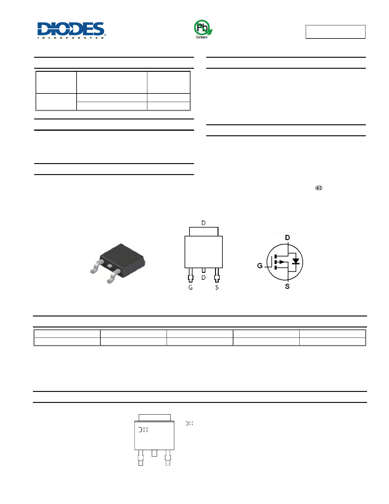
Mechanical Data
Case: TO252 (DPAK)
Case Material: Molded Plastic, “Green” Molding Compound. UL
Flammability Classification Rating 94V-0 (Note 1)
Moisture Sensitivity: Level 1 per J-STD-020
Terminals Connections: See diagram below
Terminals: Finish - Matte Tin annealed over Copper lead frame.
Solderable per MIL-STD-202, Method 208
Weight: 0.315 grams (approximate)
TO252
Top View
Top View
Pin Out
Device symbol
Ordering Information (Note 4)
Product
DMP4025LK3-13
Marking
P4025L
Reel size (inches)
13
Tape width (mm)
16
Quantity per reel
2,500
Notes:
1. EU Directive 2002/95/EC (RoHS) & 2011/65/EU (RoHS 2) compliant. All applicable RoHS exemptions applied.
2. See http://www.diodes.com/quality/lead_free.html for more information about Diodes Incorporated’s definitions of Halogen- and Antimony-free, "Green"
and Lead-free.
3. Halogen- and Antimony-free "Green” products are defined as those which contain <900ppm bromine, <900ppm chlorine (<1500ppm total Br + Cl) and
<1000ppm antimony compounds.
4. For packaging details, go to our website at http://www.diodes.com/products/packages.html.
Marking Information
YYWW
P4025L
= Manufacturer’s Marking
P4025L = Product Type Marking Code
YYWW = Date Code Marking
YY = Year (ex: 10 = 2010)
WW = Week (01 - 53)
DMP4025LK3
Document Number:35938 Rev. 3 - 2
1 of 8
www.diodes.com
March 2014
© Diodes Incorporated
1 page 
0.05
0.04
0.03
0.02
0.01
VGS = -4.5V
VGS = -10V
0.04
0.03
VGS = -10V
0.02
0.01
DMP4025LK3
TA = 150°C
TA = 125°C
TA = 85°C
TA = 25°C
TA = -55°C
0
0
1.7
1.5
1.3
1.1
5 10 15 20 25
-ID, DRAIN-SOURCE CURRENT (A)
Figure 6. Typical On-Resistance
vs. Drain Current and Gate Voltage
30
VGS = -10V
ID = -20A
VGS = -4.5V
ID = -10A
0.9
0.7
0
0
0.06
0.05
5 10 15 20 25
-ID, DRAIN CURRENT (A)
Figure 7. Typical On-Resistance
vs. Drain Current and Temperature
30
0.04
0.03
0.02
0.01
VGS = -4.5V
ID = -10A
VGS = -10V
ID = -20A
0.5
-50 -25 0 25 50 75 100 125 150
TA, AMBIENT TEMPERATURE (°C)
Figure 8. On-Resistance Variation with Temperature
2.0
1.5
1.0 ID = -1mA
ID = -250µA
0.5
0
-50 -25 0 25 50 75 100 125 150
TA, AMBIENT TEMPERATURE (°C)
Figure 10. Gate Threshold Variation vs. Ambient Temperature
0
-50 -25 0 25 50 75 100 125 150
TA, AMBIENT TEMPERATURE (°C)
Figure 9. On-Resistance Variation with Temperature
20
18
16
14 TA = 25°C
12
10
8
6
4
2
0
0.2 0.4 0.6 0.8 1.0 1.2
-VSD, SOURCE-DRAIN VOLTAGE (V)
Figure 11. Diode Forward Voltage vs. Current
DMP4025LK3
Document Number:35938 Rev. 3 - 2
5 of 8
www.diodes.com
March 2014
© Diodes Incorporated
5 Page | ||
| Páginas | Total 8 Páginas | |
| PDF Descargar | [ Datasheet DMP4025LK3.PDF ] | |
Hoja de datos destacado
| Número de pieza | Descripción | Fabricantes |
| DMP4025LK3 | 40V P-CHANNEL ENHANCEMENT MODE MOSFET | Diodes |
| Número de pieza | Descripción | Fabricantes |
| SLA6805M | High Voltage 3 phase Motor Driver IC. |
Sanken |
| SDC1742 | 12- and 14-Bit Hybrid Synchro / Resolver-to-Digital Converters. |
Analog Devices |
|
DataSheet.es es una pagina web que funciona como un repositorio de manuales o hoja de datos de muchos de los productos más populares, |
| DataSheet.es | 2020 | Privacy Policy | Contacto | Buscar |