|
|
|
PDF IRFI4020H-117P Data sheet ( Hoja de datos )
| Número de pieza | IRFI4020H-117P | |
| Descripción | DIGITAL AUDIO MOSFET | |
| Fabricantes | International Rectifier | |
| Logotipo | ||
Hay una vista previa y un enlace de descarga de IRFI4020H-117P (archivo pdf) en la parte inferior de esta página. Total 6 Páginas | ||
|
No Preview Available !
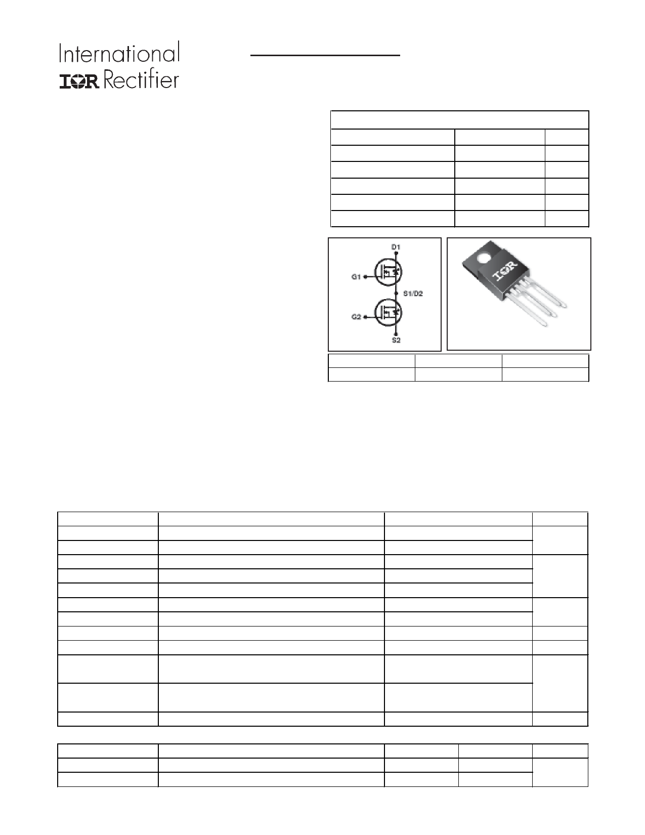
DIGITAL AUDIO MOSFET
PD - 97252
IRFI4020H-117P
Features
Integrated half-bridge package
Reduces the part count by half
Facilitates better PCB layout
Key parameters optimized for Class-D
audio amplifier applications
Low RDS(ON) for improved efficiency
Low Qg and Qsw for better THD and
improved efficiency
Low Qrr for better THD and lower EMI
Can delivery up to 300W per channel into
8Ω load in half-bridge configuration
amplifier
Lead-free package
gKey Parameters
VDS 200
RDS(ON) typ. @ 10V
80
Qg typ.
19
Qsw typ.
6.8
RG(int) typ.
3.0
TJ max
150
V
m:
nC
nC
Ω
°C
D1
G1
S1/D2
G2
S2
TO-220 Full-Pak 5 PIN
G1, G2
Gate
D1, D2
Drain
S1, S2
Source
Description
This Digital Audio MosFET Half-Bridge is specifically designed for Class D audio amplifier applications. It
consists of two power MosFET switches connected in half-bridge configuration. The latest process is used
to achieve low on-resistance per silicon area. Furthermore, Gate charge, body-diode reverse recovery,
and internal Gate resistance are optimized to improve key Class D audio amplifier performance factors
such as efficiency, THD and EMI. These combine to make this Half-Bridge a highly efficient, robust and
reliable device for Class D audio amplifier applications.
gAbsolute Maximum Ratings
Parameter
Max.
Units
VDS
VGS
ID @ TC = 25°C
ID @ TC = 100°C
IDM
PD @TC = 25°C
PD @TC = 100°C
Drain-to-Source Voltage
Gate-to-Source Voltage
Continuous Drain Current, VGS @ 10V
cContinuous Drain Current, VGS @ 10V
Pulsed Drain Current
fPower Dissipation
fPower Dissipation
200 V
±20
9.1 A
5.7
36
21 W
8.5
EAS
TJ
TSTG
dLinear Derating Factor
Single Pulse Avalanche Energy
Operating Junction and
Storage Temperature Range
0.17
130
-55 to + 150
W/°C
mJ
°C
Soldering Temperature, for 10 seconds
(1.6mm from case)
Mounting torque, 6-32 or M3 screw
gThermal Resistance
300
x x10lb in (1.1N m)
Parameter
fRθJC
Junction-to-Case
RθJA Junction-to-Ambient (free air)
Typ.
–––
–––
Max.
5.9
65
Units
°C/W
www.irf.com
1
08/22/06
1 page 
300
275 ID = 5.5A
250
225
200 TJ = 125°C
175
150
125
100 TJ = 25°C
75
50
5 6 7 8 9 10
VGS, Gate -to -Source Voltage (V)
Fig 12. On-Resistance vs. Gate Voltage
15V
VDS
L
DRIVER
RG
2V0GVS
tp
D.U.T
IAS
0.01Ω
+
- VDD
A
Fig 13b. Unclamped Inductive Test Circuit
VDS
LD
+
VDD -
VGS
Pulse Width < 1µs
Duty Factor < 0.1%
D.U.T
Fig 14a. Switching Time Test Circuit
L
VCC
DUT
0
1K
Fig 15a. Gate Charge Test Circuit
www.irf.com
IRFI4020H-117P
600
ID
500 TOP 0.91A
1.1A
BOTTOM 5.5A
400
300
200
100
0
25 50 75 100 125 150
Starting TJ , Junction Temperature (°C)
Fig 13a. Maximum Avalanche Energy vs. Drain Current
V(BR)DSS
tp
IAS
Fig 13c. Unclamped Inductive Waveforms
VDS
90%
10%
VGS
td(on) tr
td(off) tf
Fig 14b. Switching Time Waveforms
Id
Vds
Vgs
Vgs(th)
Qgs1 Qgs2 Qgd
Qgodr
Fig 15b Gate Charge Waveform
5
5 Page | ||
| Páginas | Total 6 Páginas | |
| PDF Descargar | [ Datasheet IRFI4020H-117P.PDF ] | |
Hoja de datos destacado
| Número de pieza | Descripción | Fabricantes |
| IRFI4020H-117P | DIGITAL AUDIO MOSFET | International Rectifier |
| Número de pieza | Descripción | Fabricantes |
| SLA6805M | High Voltage 3 phase Motor Driver IC. |
Sanken |
| SDC1742 | 12- and 14-Bit Hybrid Synchro / Resolver-to-Digital Converters. |
Analog Devices |
|
DataSheet.es es una pagina web que funciona como un repositorio de manuales o hoja de datos de muchos de los productos más populares, |
| DataSheet.es | 2020 | Privacy Policy | Contacto | Buscar |