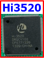
Hi3520
用户指南
目录
3.1 Reset ............................................................................................................................................................3-1
3.1.1 Overview ...........................................................................................................................................3-1
3.1.2 Reset Signal Control..........................................................................................................................3-1
3.1.3 Reset Configuration...........................................................................................................................3-2
3.2 Clock ...........................................................................................................................................................3-3
3.2.1 Overview ...........................................................................................................................................3-3
3.2.2 Clock Control ....................................................................................................................................3-3
3.2.3 Clock Configuration..........................................................................................................................3-5
3.3 Processor and Address Space Mapping of the Memory ............................................................................3-16
3.3.1 Processor .........................................................................................................................................3-16
3.3.2 Address Space Mapping of the Memory .........................................................................................3-17
3.4 Interrupt System ........................................................................................................................................3-30
3.4.1 Overview .........................................................................................................................................3-30
3.4.2 Features ...........................................................................................................................................3-30
3.4.3 Function Description .......................................................................................................................3-30
3.4.4 Register Summary ...........................................................................................................................3-34
3.4.5 Register Description........................................................................................................................3-35
3.5 Direct Memory Access Controller.............................................................................................................3-40
3.5.1 Overview .........................................................................................................................................3-40
3.5.2 Features ...........................................................................................................................................3-40
3.5.3 Function Description .......................................................................................................................3-41
3.5.4 Operating Mode...............................................................................................................................3-44
3.5.5 Register Summary ...........................................................................................................................3-45
3.5.6 Register Description........................................................................................................................3-48
3.6 CIPHER.....................................................................................................................................................3-67
3.6.1 Overview .........................................................................................................................................3-67
3.6.2 Features ...........................................................................................................................................3-67
3.6.3 Function Description .......................................................................................................................3-68
3.6.4 Operating Mode...............................................................................................................................3-78
3.6.5 Register Summary ...........................................................................................................................3-80
3.6.6 Register Description........................................................................................................................3-81
3.7 Timer .........................................................................................................................................................3-95
3.7.1 Overview .........................................................................................................................................3-95
3.7.2 Features ...........................................................................................................................................3-96
3.7.3 Function Description .......................................................................................................................3-96
3.7.4 Operating Mode...............................................................................................................................3-97
3.7.5 Register Summary ...........................................................................................................................3-98
3.7.6 Register Description........................................................................................................................3-98
3.8 Watchdog.................................................................................................................................................3-107
3.8.1 Overview .......................................................................................................................................3-107
3.8.2 Features .........................................................................................................................................3-107
3.8.3 Signal Description .........................................................................................................................3-108
文档版本 02 (2010-01-19)
海思专有和保密信息
版权所有 © 深圳市海思半导体有限公司
iii

Hi3520
用户指南
插图目录
插图目录
Figure 1-1 Logic block diagram of the Hi3520 ................................................................................................1-1
Figure 1-2 Block diagram of the Hi3520 in a 16-channel CIF DVR................................................................1-7
Figure 1-3 Block diagram of the Hi3520 in a 4-channel D1 DVR ...................................................................1-8
Figure 1-4 Block diagram of the Hi3520 in an 8-channel D1 DVR .................................................................1-9
Figure 2-1 Primitives of timing diagrams..................................................................................................... 2-111
Figure 2-2 Write timing of dqs_out relative to dq_out, CKP, and CKN ....................................................... 2-112
Figure 2-3 Write timing of dqs_out relative to CK....................................................................................... 2-112
Figure 2-4 Write timing of cmd/addr relative to CK .................................................................................... 2-112
Figure 2-5 DDR2 SDRAM output timing .................................................................................................... 2-113
Figure 2-6 100 Mbit/s receive timing of the MII interface ........................................................................... 2-114
Figure 2-7 10 Mbit/s receive timing of the MII interface ............................................................................. 2-115
Figure 2-8 100 Mbit/s transmit timing of the MII interface ......................................................................... 2-115
Figure 2-9 10 Mbit/s transmit timing of the MII interface ........................................................................... 2-115
Figure 2-10 Receive timing of the RGMII interface .................................................................................... 2-116
Figure 2-11 Transmit timing of the RGMII interface ................................................................................... 2-116
Figure 2-12 Read timing of the MDIO interface .......................................................................................... 2-117
Figure 2-13 Write timing of the MDIO interface.......................................................................................... 2-117
Figure 2-14 Timing parameter diagram of the MDIO interface ................................................................... 2-118
Figure 2-15 Transmit timing of the MDIO interface .................................................................................... 2-118
Figure 2-16 Timing of the VI interface......................................................................................................... 2-119
Figure 2-17 Timing of the VO interface ....................................................................................................... 2-119
Figure 2-18 Timing of the VO concatenated input interface ........................................................................2-120
Figure 2-19 Timing of the PCI interface (using the inside clock of the Hi3520) .........................................2-120
Figure 2-20 Timing of the PCI interface (using the external clock of the Hi3520) ......................................2-121
Figure 2-21 Transfer timing of the I2C interface ..........................................................................................2-121
Figure 2-22 Timing of the MMC Interface...................................................................................................2-122
文档版本 02 (2010-01-19)
海思专有和保密信息
版权所有 © 深圳市海思半导体有限公司
ix


