|
|
|
PDF SD4870 Data sheet ( Hoja de datos )
| Número de pieza | SD4870 | |
| Descripción | CURRENT MODE PWM CONTROLLER | |
| Fabricantes | Silan Microelectronics | |
| Logotipo | ||
Hay una vista previa y un enlace de descarga de SD4870 (archivo pdf) en la parte inferior de esta página. Total 9 Páginas | ||
|
No Preview Available !
SD4870_Datasheet
CURRENT MODE PWM CONTROLLER
DESCRIPTION
SD4870 is a current mode PWM controller IC for high performance,
low standby power offline flyback converter application.
In no load or light load condition, the IC operates in Light Load
Mode to reduce switching loss and improve efficiency.
Large value startup resistor could be used in the startup circuit to
minimize the standby current because of low startup current.
SD4870 offers complete protection functions including cycle-by-
cycle over current protection, over load protection, VDD voltage
over voltage and under voltage protection, etc.
Excellent EMI performance is achieved with frequency shuffling
technique and soft switching control at the totem pole gate driver
output.
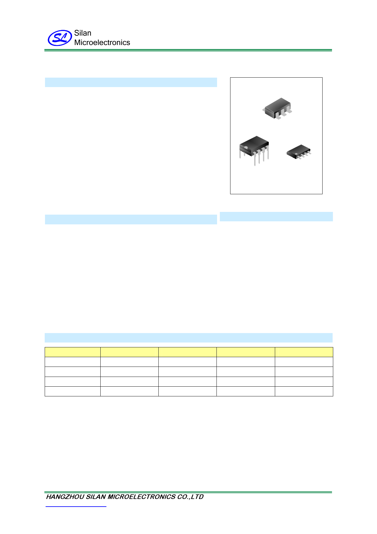
SOT-23-6L
DIP-8-300-2.54 SOP-8-225-1.27
FEATURES
* Frequency shuffling to improve EMI performance
* Light Load Mode for minimum standby power
* External programmable switching frequency
* 3uA low startup current
* Internal LEB circuit
* VDD over voltage and under voltage protection
* Gate output maximum voltage clamp
* Current limiting
* Over load protection
* SOT-23-6L/SOP8/DIP8 package
APPLICATIONS
* Battery Chargers
* Adapters
* Set-Top Box Power Supplies
ORDERING INFORMATION
Part No.
SD4870TR
SD4870A
SD4870C
SD4870CTR
Package
SOT-23-6L
DIP-8-300-2.54
SOP-8-225-1.27
SOP-8-225-1.27
Marking
4870
SD4870A
SD4870C
SD4870C
Material
Pb free
Pb free
Pb free
Pb free
Packing
Tape & Reel
Tube
Tube
Tape & Reel
HANGZHOU SILAN MICROELECTRONICS CO.,LTD
Http://www.silan.com.cn
REV:1.3 2010.12.29
Page 1 of 9
1 page 
SD4870_Datasheet
Light Load Mode
In no load or light load condition, major power loss of total power consumption is from switching loss on the
MOSFET transistor switching loss, the core loss of the transformer loss and the loss on the external snubber
circuit loss become the majority in total power loss. The value of those power loss is proportional to switching
actions within a fixed period of time. So reducing number of switching actions leads to reduction of power loss.
SD4870 enters Light Load Mode in no load or light load condition. The gate drive output switches only when
output DC voltage drops below a present level and the switching frequency reduces. Otherwise the gate drive
remains at off state.
Oscillation Frequency Setting
The oscillation frequency is determined by resistor connected between RI and GND. The relationship between
the value of this resistor and frequency are shown below
fS
=
6500
RRI
(kHz) ,
where
RRI
is
the
value
of
external
resistor
and
its
unit
is
KΩ.
Current Sense and LEB
At switching leading edge time, the current spike due to Snubber diode reverse recovery should be chopped off.
And this is available through internal LEB (Leading Edge Blanking) circuit. So that the external RC filter circuit on
SENSE input is no longer required.
During the blanking period, the PWM comparator and OC comparator are disabled and MOSFET transistor
keeps turn-on state if MOSFET turns on. The minimum on time of MOSFET is LEB time.
Gate Drive
GATE pin is connected to external MOSFET’s gate for switch control. Too weak the gate drive ability results in
more switch loss of MOSFET while too strong gate drive compromises the EMI performance.
A good tradeoff is achieved through the totem pole gate drive design with appropriate output ability and dead
time control.
Protection controls
SD4870 offers complete protection functions including cycle-by-cycle over current protection, over load protection,
VDD input voltage over voltage and under voltage protection, etc.
Constant output power limit over universal input voltage range is achived with over current protection threshold
line voltage compensation to over current protection threshold.
VDD is supplies by transformer auxiliary winding output. It is clamped when VDD is higher than clamp threshold
value. The MOSFET is shut down when VDD drops below UVLO threshold voltage and IC enters power on
startup sequence thereafter.
When FB input voltage is higher than over load threshold voltage for more than TD_OL, the MOSFET is shut
down and VDD voltage drops. IC restarts when VDD is lower than UVLO threshold voltage.
HANGZHOU SILAN MICROELECTRONICS CO.,LTD
Http://www.silan.com.cn
REV:1.3 2010.12.29
Page 5 of 9
5 Page | ||
| Páginas | Total 9 Páginas | |
| PDF Descargar | [ Datasheet SD4870.PDF ] | |
Hoja de datos destacado
| Número de pieza | Descripción | Fabricantes |
| SD4870 | CURRENT MODE PWM CONTROLLER | Silan Microelectronics |
| SD4870A | CURRENT MODE PWM CONTROLLER | Silan Microelectronics |
| SD4870C | CURRENT MODE PWM CONTROLLER | Silan Microelectronics |
| SD4870CTR | CURRENT MODE PWM CONTROLLER | Silan Microelectronics |
| Número de pieza | Descripción | Fabricantes |
| SLA6805M | High Voltage 3 phase Motor Driver IC. |
Sanken |
| SDC1742 | 12- and 14-Bit Hybrid Synchro / Resolver-to-Digital Converters. |
Analog Devices |
|
DataSheet.es es una pagina web que funciona como un repositorio de manuales o hoja de datos de muchos de los productos más populares, |
| DataSheet.es | 2020 | Privacy Policy | Contacto | Buscar |