|
|
|
PDF HCPL2219 Data sheet ( Hoja de datos )
| Número de pieza | HCPL2219 | |
| Descripción | Low Input Current Logic Gate Optocouplers | |
| Fabricantes | Avago | |
| Logotipo | ||
Hay una vista previa y un enlace de descarga de HCPL2219 (archivo pdf) en la parte inferior de esta página. Total 13 Páginas | ||
|
No Preview Available !
HCPL-2200, HCPL-2219
Low Input Current Logic Gate Optocouplers
Data Sheet
Description
The HCPL-2200/2219 are optically coupled logic gates
that combine a GaAsP LED and an integrated high gain
photo detector. The detector has a three state output
stage and has a detector threshold with hysteresis. The
three state output eliminates the need for a pullup
resistor and allows for direct drive of data busses. The
hysteresis provides differential mode noise immunity
and eliminates the potential for output signal chatter.
Asuperiorinternalshieldon theHCPL-2219guarantees
common mode transient immunity of 2.5 kV/µs at a
common mode voltage of 400 volts.
The Electrical and Switching Characteristics of the
HCPL-2200/2219 are guaranteed over the tempera-
ture range of 0° C to 85° C and a VCC range of 4.5 volts to
20 volts. Low IF and wide VCC range allow compatibility
with TTL, LSTTL, and CMOS logic and result in lower
power consumption compared to other high speed
optocouplers. Logic signals are transmitted with a
typical propagation delay of 160 nsec.
The HCPL-2200/2219 are useful for isolating high
speed logic interfaces, buffering of input and output
lines, and implementing isolated line receivers in
high noise environments.
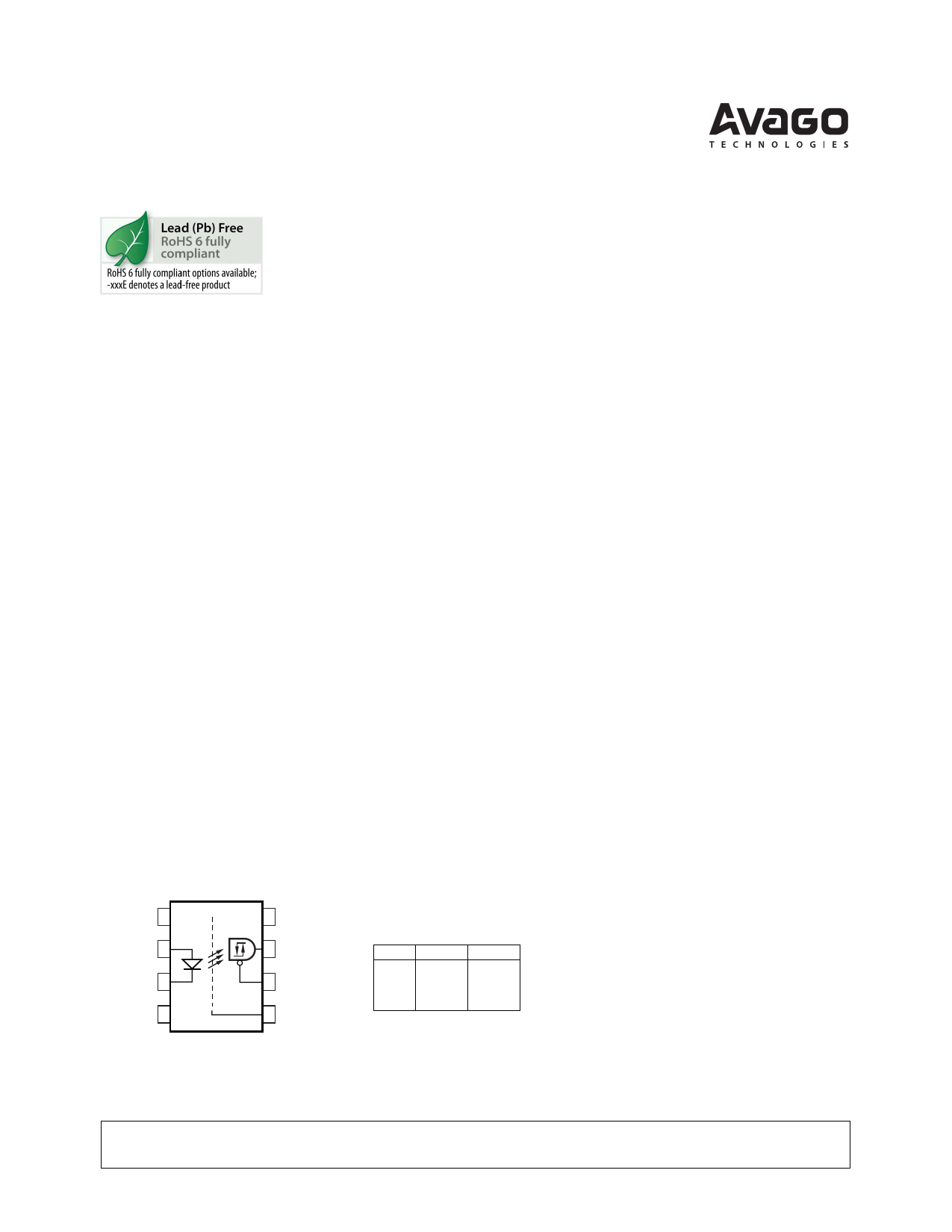
Functional Diagram
Features
• 2.5 kV/µs minimum Common Mode Rejection (CMR) at
VCM = 400 V (HCPL-2219)
• Compatible with LSTTL, TTL, and CMOS logic
• Wide VCC range (4.5 to 20 V)
• 2.5 Mbd guaranteed over temperature
• Low input current (1.6 mA)
• Three state output (no pullup resistor required)
• Guaranteed performance from 0°C to 85°C
• Hysteresis
• Safety approval
– UL recognized -3750 V rms for 1 minute
– CSA approved
– IEC/EN/DIN EN 60747-5-2 approved with
VIORM = 630 V peak (HCPL-2219 Option 060 only)
• MIL-PRF-38534 hermetic version available
(HCPL-5200/1)
Applications
• Isolation of high speed logic systems
• Computer-peripheral interfaces
• Microprocessor system interfaces
• Ground loop elimination
• Pulse transformer replacement
• Isolated buss driver
• High speed line receiver
NC 1
ANODE 2
CATHODE 3
NC 4
SHIELD
8 VCC
7 VO
6 VE
5 GND
TRUTH TABLE
(POSITIVE LOGIC)
LED ENABLE OUTPUT
ON
OFF
ON
OFF
H
H
L
L
Z
Z
H
L
A 0.1 µF bypass capacitor must be connected between pins 5 and 8.
CAUTION: It is advised that normal static precautions be taken in handling and assembly of this
component to prevent damage and/or degradation which may be induced by ESD.
1 page 
Solder Reflow Thermal Profile
300
PREHEATING RATE 3°C + 1°C/–0.5°C/SEC.
REFLOW HEATING RATE 2.5°C ± 0.5°C/SEC. PEAK
TEMP.
245°C
200
160°C
150°C
140°C
100
2.5°C ± 0.5°C/SEC.
3°C + 1°C/–0.5°C
PREHEATING TIME
150°C, 90 + 30 SEC.
30
SEC.
30
SEC.
PEAK
TEMP.
240°C
PEAK
TEMP.
230°C
SOLDERING
TIME
200°C
50 SEC.
ROOM
TEMPERATURE
0
0
TIGHT
TYPICAL
LOOSE
50 100 150 200 250
TIME (SECONDS)
Note: Non-halide flux should be used.
Recommended Pb-Free IR Profile
Tp 260 +0/-5 °C
TL 217 °C
RAMP-UP
3 °C/SEC. MAX.
Tsmax 150 - 200 °C
Tsmin
ts
PREHEAT
60 to 180 SEC.
tp
tL
TIME WITHIN 5 °C of ACTUAL
PEAK TEMPERATURE
20-40 SEC.
RAMP-DOWN
6 °C/SEC. MAX.
60 to 150 SEC.
Regulatory Information
The HCPL-2200/2219 have been
approved by the following
organizations:
UL
Recognized under UL 1577,
Component Recognition Program,
File E55361.
CSA
Approved under CSA Component
Acceptance Notice #5, File CA
88324.
IEC/EN/DIN EN 60747-5-2
Approved under:
IEC 60747-5-2:1997 + A1:2002
EN 60747-5-2:2001 + A1:2002
DIN EN 60747-5-2 (VDE 0884
Teil 2):2003-01.
(Option 060 only)
25
t 25 °C to PEAK
TIME
NOTES:
THE TIME FROM 25 °C to PEAK TEMPERATURE = 8 MINUTES MAX.
Tsmax = 200 °C, Tsmin = 150 °C
Note: Non-halide flux should be used.
Insulation and Safety Related Specifications
Parameter
Symbol Value Units Conditions
Min. External Air Gap L(IO1) 7.1 mm Measured from input terminals to output terminals,
(External Clearance)
shortest distance through air.
Min. External
L(IO2) 7.4 mm Measured from input terminals to output terminals,
Tracking Path
shortest distance path along body.
(External Creepage)
Minimum Internal
Plastic Gap
(Internal Clearance)
0.08 mm Through insulation distance, conductor to conductor,
usually the direct distance between the photoemitter
and photodetector inside the optocoupler cavity.
Tracking Resistance CTI 200 V DIN IEC 112/VDE 0303 Part 1
(Comparative
Tracking Index)
Isolation Group
IIIa Material Group (DIN VDE 0110, 1/89, Table 1)
Option 300 – surface mount classification is Class A in accordance with CECC 00802.
5
5 Page 
250
VCC = 5 V
C1 (120 pF) PEAKING
CAPACITOR IS USED.
200 SEE FIGURE 5.
150
tPHL
IF (mA)
5
3
1.6
1.6
3
5
100
tPLH
50
-60 -40 -20
0
20 40 60 80 100
TA – TEMPERATURE – °C
Figure 6. Typical propagation delays vs.
temperature.
PULSE
GENERATOR
ZO = 50 Ω
tr = tf = 5 ns
CL= 15 pF INCLUDING PROBE
AND JIG CAPACITANCES.
VCC
HCPL-2200
VO
+5 V
S1
1 VCC 8
IF 2
7
D1 619 Ω
INPUT VC
MONITORING
NODE
3
4
6
GND 5
CL
5 kΩ
D2
D3
D4
S2
D1-4 ARE 1N916 OR 1N3064.
INPUT
VE
tPZL
OUTPUT
VO
OUTPUT
VO
S1 CLOSED
S2 OPEN
tPZH
S1 OPEN
S2 CLOSED
tPLZ
1.3 V 0.5 V
0.5 V
1.3 V
0V
tPHZ
3.0 V
1.3 V
0V
S1 AND
S2 CLOSED
VOL
VOH
≈1.5 V
S1 AND
S2 CLOSED
Figure 7. Test circuit for tPHZ, tPZH, tPLZ, and tPZL.
100
CL = 15 pF
80
60 tPLZ
40
tPZL
20
VCC
20 V
4.5 V
20 V
4.5 V
0
-60 -40 -20 0 20 40 60 80 100
TA – TEMPERATURE – °C
Figure 8. Typical logic low enable
propagation delay vs. temperature.
200
CL = 15 pF
VCC
150 20 V
tPHZ
4.5 V
100
20 V
50
tPZH
4.5 V
0
-60 -40 -20 0 20 40 60 80 100
TA – TEMPERATURE – °C
Figure 9. Typical logic high enable
propagation delay vs. temperature.
120
VCC = 5 V
C2 = 15 pF
100
80
60
tr
40
20
tf
0
-60 -40 -20 0 20 40 60 80 100
TA – TEMPERATURE – °C
Figure 10. Typical rise, fall time vs.
temperature.
11
11 Page | ||
| Páginas | Total 13 Páginas | |
| PDF Descargar | [ Datasheet HCPL2219.PDF ] | |
Hoja de datos destacado
| Número de pieza | Descripción | Fabricantes |
| HCPL2211 | (HCPL-xxxx) Very High CMR / Wide VCC Logic Gate Optocouplers | Hewlett-Packard |
| HCPL2211 | Logic Gate Optocouplers | Avago |
| HCPL2212 | (HCPL-xxxx) Very High CMR / Wide VCC Logic Gate Optocouplers | Hewlett-Packard |
| HCPL2212 | Logic Gate Optocouplers | Avago |
| Número de pieza | Descripción | Fabricantes |
| SLA6805M | High Voltage 3 phase Motor Driver IC. |
Sanken |
| SDC1742 | 12- and 14-Bit Hybrid Synchro / Resolver-to-Digital Converters. |
Analog Devices |
|
DataSheet.es es una pagina web que funciona como un repositorio de manuales o hoja de datos de muchos de los productos más populares, |
| DataSheet.es | 2020 | Privacy Policy | Contacto | Buscar |