|
|
|
PDF TA2002F Data sheet ( Hoja de datos )
| Número de pieza | TA2002F | |
| Descripción | STEREO HEADPHONE AMPLIFIER (3V USE) | |
| Fabricantes | Toshiba | |
| Logotipo | ||
Hay una vista previa y un enlace de descarga de TA2002F (archivo pdf) en la parte inferior de esta página. Total 18 Páginas | ||
|
No Preview Available !
TA2002F / FN
TOSHIBA Bipolar Linear Integrated Circuit Silicon Monolithic
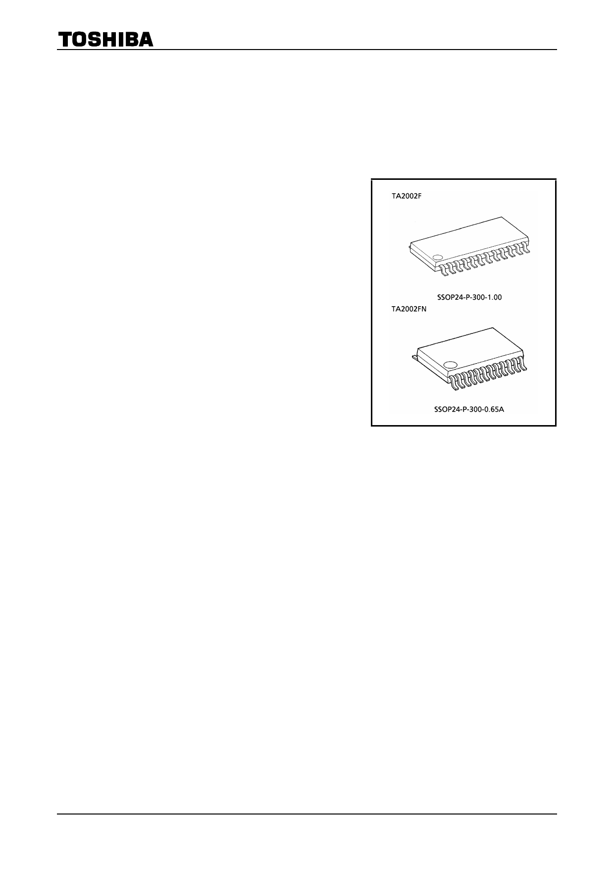
TA2002F,TA2002FN
Stereo Headphone Amplifier (3V USE)
The TA2002F, TA2002FN are developed for play−back stereo
headphone equipments (3V use).
They are built in dual auto−reverse preamplifier, dual OCL
power amplifier, and a ripple filter.
Features
Power amplifier stage
· OCL (output condenser−less)
· Low noise: Vno = 22µVrms (typ.)
· Excellent ripple rejection ratio: RR = 62dB (typ.)
· Voltage gain: GV = 27dB (typ.)
· Built−in a power amplifier mute
· Built−in input capacitor for reducing buzz noise
Preamplifier stage
· Auto−reverse with F / R control switch
· Input coupling condenser−less
· Low noise: Vni = 1.3µVrms (typ.)
· Built−in a preamplifier mute
· Built−in input capacitor for reducing buzz noise
Total
· Built−in a ripple filter
Weight
SSOP24−P−300−1.00
SSOP24−P−300−0.65A
· Built−in a power switch
· Low quiescent current : ICCQ = 11.5mA (typ.) (VCC = 3V, Ta = 25°C)
· Operating supply voltage range: VCC (opr) = 1.8~4.5V (Ta = 25°C)
: 0.32 g (typ.)
: 0.14 g (typ.)
1 2002-10-30
1 page 
TA2002F / FN
Application Note
(1) PW SW
It is necessary to connect an external pull-down resistor with the terminal PW SW (pin (8)), in case that this IC
is turned on due to external noise etc.
(2) PW MUTE
The leak current flows through the terminal of PW MUTE (pin(9)), in
case that the terminal is connected with VCC line independently, even
though this IC is off-mode (the terminal of PW SW (pin(8)) is off-mode).
It is advised to connect R1 and C with the terminal of PW MUTE, to
reduce a pop sound in switchover between PW mute on / off. And it is
advised to connect R2, to shorten a switchover time from PW MUTE
off-mode to PW MUTE on-mode (see Fig.1). It is better that the
constants are R1≒R2≒100kΩ, C≒1µF at VCC = 3V.
As for the constants, select the optimum one depending on each a set
carefully.
VCC
R1
R2 C
9
Fig.1 PW mute circuit
reducing a pop
sound
(3) F / R SW
The terminal of F / R SW (pin(10)) should not be applied to higher voltage than V17 (RF OUT), because the
ripple filter circuit supplies the F / R SW circuit with power source. And in reverse mode, the terminal of F / R
SW should be connected with GND line through R3 (180~270kΩ) , because the F / R SW circuit doesn't operate
normally. It is advised to connect an external capacitor (C3≒1µF), in order to reduce a pop sound in switchover
between F / R mode (see Fig.2). As for the constants, select the optimum one depending on each a set carefully.
RF OUT
17
R4
1kΩ
18
C4 PRE
SW
100kΩ
330kΩ
1kΩ
F / R SW
10
R3
C3
Fig.2 Internal equivalent circuit of F / R SW and PRE SW and the external circuits reducing a pop sound in
switchover.
5 2002-10-30
5 Page 
TA2002F / FN
Characteristics Curves
Unless Otherwise Specified: VCC = 3V, f = 1kHz, Ta = 25°C
Power amplifier Stage: Rg = 600Ω, RL = 16Ω
Preamplifier Stage: Rg = 2.2kΩ, RL = 10kΩ
ICCQ – VCC
VO – VCC
12
Vin = 0
8
3
VRF
2
PW MUTE ON
4
1 VO(C), VREF
0 23 4 5
Supply voltage VCC (V)
0 23 4 5
Supply voltage VCC (V)
PW
THD = 10%
60
40
20
Po – VCC
RL = 16Ω
RL = 32Ω
0 23 4 5
Supply voltage VCC (V)
PW THD1 – Po
20
10
5
2
1
f = 10kHz
0.5 f = 100Hz
0.2
f = 1kHz
0.2 0.5 1 2
5 10 20
Output power Po (mW)
50 100
PW
Vo = − 12dBV
40
GV – f
30
20
20 50 100 200 500 1k 2k 5k 10k 20k
Frequency f (Hz)
PW
0
Vo = − 12dBV
20
CT1 – f
40
60
80
20 50 100 200 500 1k 2k 5k 10k 20k
Frequency f (Hz)
11 2002-10-30
11 Page | ||
| Páginas | Total 18 Páginas | |
| PDF Descargar | [ Datasheet TA2002F.PDF ] | |
Hoja de datos destacado
| Número de pieza | Descripción | Fabricantes |
| TA2002 | STEREO HEADPHONE AMPLIFIER (3V USE) | Toshiba |
| TA2002F | STEREO HEADPHONE AMPLIFIER (3V USE) | Toshiba |
| TA2002FN | STEREO HEADPHONE AMPLIFIER (3V USE) | Toshiba |
| Número de pieza | Descripción | Fabricantes |
| SLA6805M | High Voltage 3 phase Motor Driver IC. |
Sanken |
| SDC1742 | 12- and 14-Bit Hybrid Synchro / Resolver-to-Digital Converters. |
Analog Devices |
|
DataSheet.es es una pagina web que funciona como un repositorio de manuales o hoja de datos de muchos de los productos más populares, |
| DataSheet.es | 2020 | Privacy Policy | Contacto | Buscar |