|
|
|
PDF LIS3L02AS4TR Data sheet ( Hoja de datos )
| Número de pieza | LIS3L02AS4TR | |
| Descripción | MEMS INERTIAL SENSOR / LINEAR ACCELEROMETER | |
| Fabricantes | STMicroelectronics | |
| Logotipo | ||
Hay una vista previa y un enlace de descarga de LIS3L02AS4TR (archivo pdf) en la parte inferior de esta página. Total 14 Páginas | ||
|
No Preview Available !
LIS3L02AS4
MEMS INERTIAL SENSOR:
3-Axis - ±2g/±6g LINEAR ACCELEROMETER
1 Features
■ 2.4V TO 3.6V SINGLE SUPPLY OPERATION
■ LOW POWER CONSUMPTION
■ ±2g/±6g USER SELECTABLE FULL-SCALE
■ 0.5mg RESOLUTION OVER 100Hz
BANDWIDTH
■ EMBEDDED SELF TEST AND POWER DOWN
■ OUTPUT VOLTAGE, OFFSET AND
SENSITIVITY RATIOMETRIC TO THE
SUPPLY VOLTAGE
■ HIGH SHOCK SURVIVABILITY
■ LEAD FREE AND ECOPACK COMPATIBLE
Figure 1. Package
SO24
Table 1. Order Codes
Part Number
Package
E-LIS3L02AS4
SO24
E-LIS3L02AS4TR SO24
Finishing
Tube
Tape & Reel
2 Description
The LIS3L02AS4 is a low-power three axes linear ac-
celerometer that includes a sensing element and an
IC interface able to take the information from the
sensing element and to provide an analog signal to
the external world.
The sensing element, capable of detecting the accel-
eration, is manufactured using a dedicated process
developed by ST to produce inertial sensors and ac-
tuators in silicon.
The IC interface is manufactured using a standard
CMOS process that allows high level of integration to
design a dedicated circuit which is trimmed to better
match the sensing element characteristics.
The LIS3L02AS4 has a user selectable full scale of
±2g, ±6g and it is capable of measuring accelerations
over a bandwidth of 1.5KHz for all axes. The device
bandwidth may be reduced by using external capac-
itances. A self-test capability allows to check the me-
chanical and electrical signal path of the sensor.
The LIS3L02AS4 is available in plastic SMD package
and it is specified over an extended temperature
range of -40°C to +85°C.
The LIS3L02AS4 belongs to a family of products suit-
able for a variety of applications:
– Mobile terminals
– Gaming and Virtual Reality input devices
– Free-fall detection for data protection
– Antitheft systems and Inertial Navigation
– Appliance and Robotics
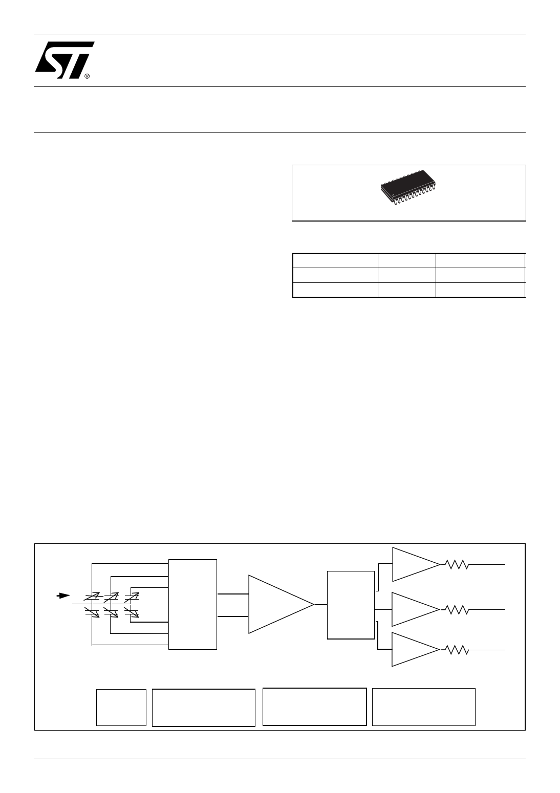
Figure 2. Block Diagram
X+ Routx Voutx
CHARGE
S/H
Y+ AMPLIFIER
Z+
a MUX
Z-
Y-
X-
DEMUX
S/H
S/H
Routy Vouty
Routz Voutz
SELF TEST
REFERENCE
TRIMMING CIRCUIT
December 2005
CLOCK
Rev. 2
1/14
1 page 
LIS3L02AS4
3.1 Terminology
3.1.1 Sensitivity
Describes the gain of the sensor and can be determined by applying 1g acceleration to it. As the sensor
can measure DC accelerations this can be done easily by pointing the axis of interest towards the center
of the earth, note the output value, rotate the sensor by 180 degrees (point to the sky) and note the output
value again thus applying ±1g acceleration to the sensor. Subtracting the larger output value from the
smaller one and dividing the result by 2 will give the actual sensitivity of the sensor. This value changes
very little over temperature (see sensitivity change vs. temperature) and also very little over time. The Sen-
sitivity Tolerance describes the range of Sensitivities of a large population of sensors.
3.1.2 Zero-g level
Describes the actual output signal if there is no acceleration present. A sensor in a steady state on an
horizontal surface will measure 0g in X axis and 0g in Y axis whereas the Z axis will measure +1g. The
output is ideally for a 3.3V powered sensor Vdd/2 = 1650mV. A deviation from ideal 0-g level (1650mV in
this case) is called Zero-g offset. Offset of precise MEMS sensors is to some extend a result of stress to
the sensor and therefore the offset can slightly change after mounting the sensor onto a printed circuit
board or exposing it to extensive mechanical stress. Offset changes little over temperature - see "Zero-g
Level Change vs. Temperature" - the Zero-g level of an individual sensor is very stable over lifetime. The
Zero-g level tolerance describes the range of zero-g levels of a population of sensors.
3.1.3 Self Test
Self Test allows to test the mechanical and electric part of the sensor, allowing the seismic mass to be moved
by means of an electrostatic test-force. The Self Test function is off when the ST pin is connected to GND. When
the ST pin is tied at Vdd an actuation force is applied to the sensor, simulating a definite input acceleration. In
this case the sensor outputs will exhibit a voltage change in their DC levels which is related to the selected full
scale and depending on the Supply Voltage through the device sensitivity. When ST is activated, the device
output level is given by the algebraic sum of the signals produced by the acceleration acting on the sensor and
by the electrostatic test-force. If the output signals change within the amplitude specified inside Table 3, than
the sensor is working properly and the parameters of the interface chip are within the defined specification.
3.1.4 Output impedance
Describes the resistor inside the output stage of each channel. This resistor is part of a filter consisting of
an external capacitor of at least 320pF and the internal resistor. Due to the high resistor level only small,
inexpensive external capacitors are needed to generate low corner frequencies. When interfacing with an
ADC it is important to use high input impedance input circuitries to avoid measurement errors. Note that
the minimum load capacitance forms a corner frequency beyond the resonance frequency of the sensor.
For a flat frequency response a corner frequency well below the resonance frequency is recommended.
In general the smallest possible bandwidth for an particular application should be chosen to get the best
results.
5/14
5 Page 
6.3 Electrical Characteristics at 25°C
Figure 18. Noise density at 3.3V (X,Y axes)
35
30
25
20
15
10
5
0
18 20 22 24 26 28 30 32
Noise density (ug/sqrt(Hz))
Figure 19. Noise density at 3.3V (Z axis)
25
20
15
10
5
0
20 30 40 50 60 70 80
Noise density (ug/sqrt(Hz))
LIS3L02AS4
Figure 20. Current consumption at 3.3V
20
18
16
14
12
10
8
6
4
2
0
0.4 0.6 0.8 1 1.2 1.4
current consumption (mA)
Figure 21. Current consumption in power
down mode at 3.3V
30
25
20
15
10
5
0
1.2 1.3 1.4 1.5 1.6 1.7 1.8
current consumption (uA)
11/14
11 Page | ||
| Páginas | Total 14 Páginas | |
| PDF Descargar | [ Datasheet LIS3L02AS4TR.PDF ] | |
Hoja de datos destacado
| Número de pieza | Descripción | Fabricantes |
| LIS3L02AS4TR | MEMS INERTIAL SENSOR / LINEAR ACCELEROMETER | STMicroelectronics |
| Número de pieza | Descripción | Fabricantes |
| SLA6805M | High Voltage 3 phase Motor Driver IC. |
Sanken |
| SDC1742 | 12- and 14-Bit Hybrid Synchro / Resolver-to-Digital Converters. |
Analog Devices |
|
DataSheet.es es una pagina web que funciona como un repositorio de manuales o hoja de datos de muchos de los productos más populares, |
| DataSheet.es | 2020 | Privacy Policy | Contacto | Buscar |