|
|
|
PDF 20N60S1 Data sheet ( Hoja de datos )
| Número de pieza | 20N60S1 | |
| Descripción | FMP20N60S1 | |
| Fabricantes | Fuji Electric | |
| Logotipo | ||
Hay una vista previa y un enlace de descarga de 20N60S1 (archivo pdf) en la parte inferior de esta página. Total 7 Páginas | ||
|
No Preview Available !
FMP20N60S1
Super J-MOS series
http://www.fujielectric.com/products/semiconductor/
FUJI POWER MOSFET
N-Channel enhancement mode power MOSFET
Features
Low on-state resistance
Low switching loss
easy to use (more controllabe switching dV/dt by Rg)
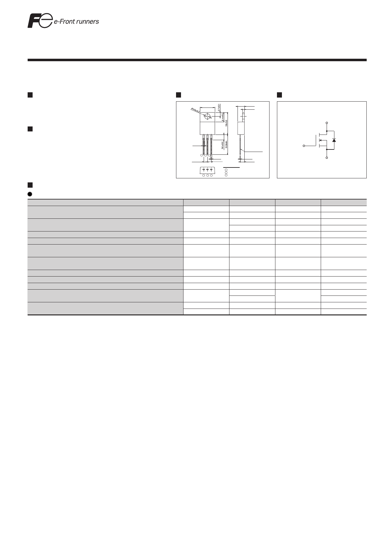
Outline Drawings [mm]
TO-220
3.6± 0.2
10
+0.5
0
4.5±0.2
1.3±0.2
Applications
UPS
Server
Telecom
Power conditioner system
Power supply
1.2 ± 0.2
1
2.54 ± 0.2
23
0.8
+0.2
-0.1
2.54± 0.2
PRE-SOLDER
0.4
+0.2
0
2.7±0.2
1 23
CONNECTION
1 GATE
2 DRAIN
3 SOURCE
JEDEC : TO-220AB
DIMENSIONS ARE IN
MILLIMETERS.
Maximum Ratings and Characteristics
Absolute Maximum Ratings at TC=25°C (unless otherwise specified)
Description
Drain-Source Voltage
Symbol
VDS
VDSX
Continuous Drain Current
ID
Pulsed Drain Current
Gate-Source Voltage
Repetitive and Non-Repetitive
Maximum Avalanche Current
Non-Repetitive
Maximum Avalanche Energy
Maximum Drain-Source dV/dt
Peak Diode Recovery dV/dt
Peak Diode Recovery -di/dt
IDP
VGS
IAR
EAS
dVDS/dt
dV/dt
-di/dt
Maximum Power Dissipation
PD
Operating and Storage Temperature range
Note *1 : Limited by maximum channel temperature.
Note *2 : Tch≤150°C, See Fig.1 and Fig.2
Note *3 : Starting Tch=25°C, IAS=2A, L=216mH, VDD=60V, RG=50Ω, See Fig.1 and Fig.2
EAS limited by maximum channel temperature and avalanche current.
Note *4 : IF≤-ID, -di/dt=100A/μs, VDD≤400V, Tch≤150°C.
Note *5 : IF≤-ID, dV/dt=15kV/μs, VDD≤400V, Tch≤150°C.
Tch
Tstg
Characteristics
600
600
±20
±12.6
±60
±30
6.6
472.2
50
15
100
2.02
150
150
-55 to +150
Equivalent circuit schematic
Drain(D)
Gate(G)
Source(S)
Unit
V
V
A
A
A
V
A
mJ
kV/μs
kV/μs
A/μs
W
°C
°C
Remarks
VGS=-30V
Tc=25°C
Tc=100°C
Note*1
Note*1
Note *2
Note *3
VDS≤ 600V
Note *4
Note *5
Ta=25°C
TC=25°C
1
1 page 
FMP20N60S1
Typical Coss stored energy
14
12
10
8
6
4
2
0
0 100 200 300 400 500 600
VDS [V]
Typical Gate Charge Characteristics
VGS= f(Qg): ID=20A, Vdd=480V, Tch=25°C
10
8
6
4
2
0
0 10 20 30 40 50 60
Qg [nC]
Transient Thermal Impedance
Zth(ch-c)= f(t): D=0
101
FUJI POWER MOSFET
http://www.fujielectric.com/products/semiconductor/
Typical Switching Characteristics vs. ID Tch=25
t= f(ID): Vdd=400V, VGS=10V/0V, RG=27Ω, L=500uH
103
tr
102 td(off)
tf
td(on)
101
100
101
ID [A]
102
Maximum Avalanche Energy vs. startingTch
E(AV)= f(starting Tch): VCC=60V, I(AV)<=6.6A
500
IAS =2A
450
400
350
300
250 IAS=4A
200
IAS =6.6A
150
100
50
0
0 25 50 75 100 125 150
starting Tch [°C]
100
10-1
10-2
10-3
10-6
10-5
10-4
10-3
10-2
10-1
t [sec]
100
5
5 Page | ||
| Páginas | Total 7 Páginas | |
| PDF Descargar | [ Datasheet 20N60S1.PDF ] | |
Hoja de datos destacado
| Número de pieza | Descripción | Fabricantes |
| 20N60S1 | FMP20N60S1 | Fuji Electric |
| 20N60S5 | SPP20N60S5 | Infineon Technologies |
| Número de pieza | Descripción | Fabricantes |
| SLA6805M | High Voltage 3 phase Motor Driver IC. |
Sanken |
| SDC1742 | 12- and 14-Bit Hybrid Synchro / Resolver-to-Digital Converters. |
Analog Devices |
|
DataSheet.es es una pagina web que funciona como un repositorio de manuales o hoja de datos de muchos de los productos más populares, |
| DataSheet.es | 2020 | Privacy Policy | Contacto | Buscar |