|
|
|
PDF A1227 Data sheet ( Hoja de datos )
| Número de pieza | A1227 | |
| Descripción | Hall Effect Latch for High Temperature Operation | |
| Fabricantes | Allegro MicroSystems | |
| Logotipo | ||
Hay una vista previa y un enlace de descarga de A1227 (archivo pdf) en la parte inferior de esta página. Total 13 Páginas | ||
|
No Preview Available !
A1225, A1227, and A1229
Hall Effect Latch for High Temperature Operation
Features and Benefits
▪ Symmetrical switchpoints
▪ Superior temperature stability
▪ Operation from unregulated supply
▪ Open-drain 25 mA output
▪ Reverse Battery protection
▪ Activate with small, commercially available
permanent magnets
▪ Solid-state reliability
▪ Small size
▪ Resistant to physical stress
▪ Enhanced ESD structures result in 8 kV HBM ESD
performance without external protection components
▪ Internal protection circuits enable 40 V load dump
compliance without external protection components
Packages:
3-pin SIP
(suffix UA)
Not to scale
3-pin SOT89
(suffix LT)
Description
These Hall-effect latches are extremely temperature-stable
and stress resistant sensor ICs especially suited for operation
over extended temperature ranges to 150°C. Superior high-
temperature performance is made possible through a novel
Schmitt trigger circuit that maintains operate and release
point symmetry by compensating for temperature changes
in the Hall element. Additionally, internal compensation
provides magnetic switchpoints that become more sensitive
with temperature, hence offsetting the usual degradation of
the magnetic field with temperature. The symmetry capability
makes these devices ideal for use in pulse-counting applications
where duty cycle is an important parameter. The three basic
devices (A1225, A1227, and A1229) are identical except for
magnetic switchpoints.
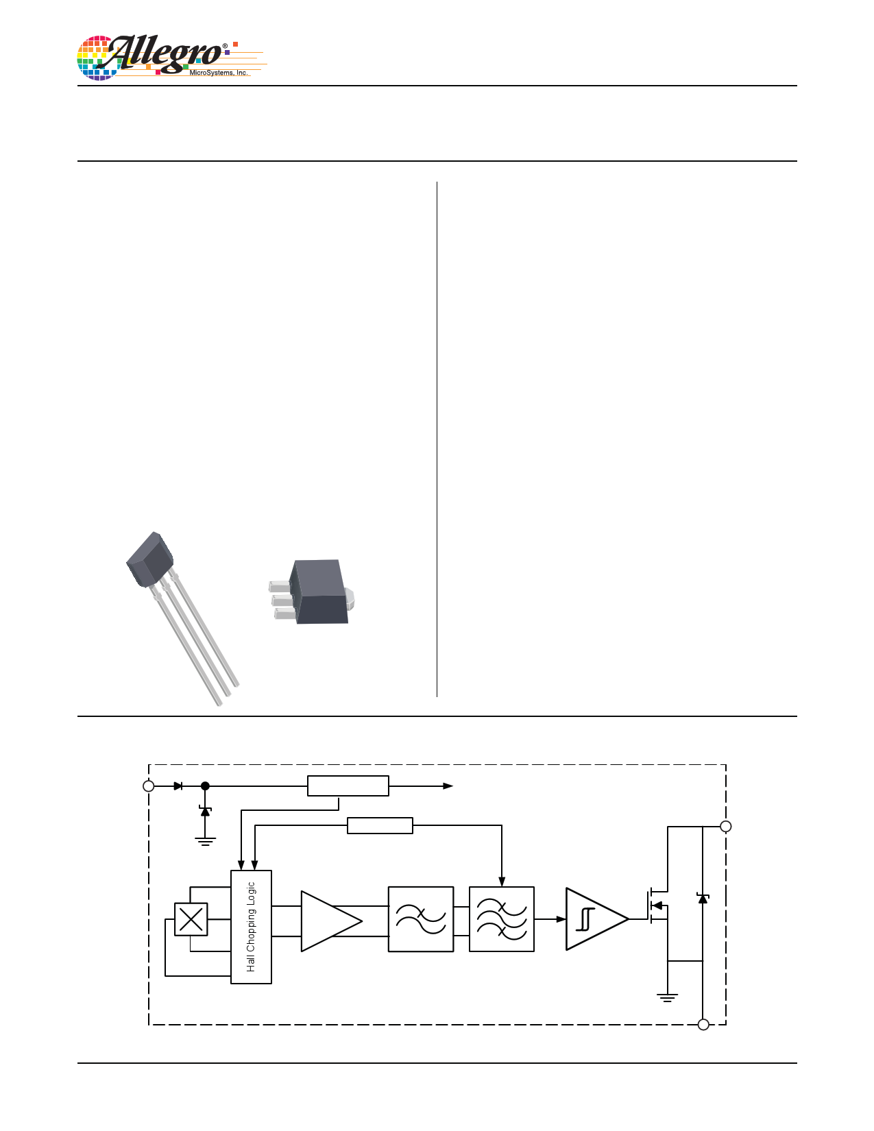
Each device includes on a single silicon chip a voltage regulator,
Hall-voltage generator, temperature compensation circuit,
signal amplifier, Schmitt trigger, and a buffered open-drain
output to sink up to 25 mA. The on-board regulator permits
operation with supply voltages of 3.8 to 24 V.
The first character of the part number suffix determines the
device operating temperature range. Suffix L is for –40°C to
150°C. Two package styles provide a magnetically optimized
package for most applications. Suffix LT is a miniature SOT89/
TO-243AAtransistor package for surface-mount applications,
suffix UAis a three-lead ultra-mini-SIP. Both packages are lead
(Pb) free with 100% matte tin leadframe plating.
Functional Block Diagram
VCC
Regulator
Clock / Logic
To All Subcircuits
VOUT
A1225-DS, Rev. 1
AMP
Anti-aliasing
LP-Filter
Tuned Filter
GND
1 page 
A1225, A1227
and A1229
Hall Effect Latch for High Temperature Operation
Characteristic Performance
A1225, A1227, and A1229 Electrical Characteristics
Average Supply Current (On) versus Ambient Temperature
6.0
5.5
5.0
4.5
4.0 VCC (V)
3.5 3.8
3.0 4.5
2.5 12
2.0 24
1.5
1.0
0.5
0
- 60 - 40 - 20 0 20 40 60 80 100 120 140 160
TA (°C)
Average Supply Current (On) versus Supply Voltage
6.0
5.5
5.0
4.5
4.0
3.5
3.0
2.5
2.0
1.5
1.0
0.5
0
2
TA (°C)
–40
25
150
6 10 14 18 22 26
VCC (V)
Average Supply Current (Off) versus Ambient Temperature
6.0
5.5
5.0
4.5
4.0 VCC (V)
3.5 3.8
3.0 4.5
2.5 12
2.0 24
1.5
1.0
0.5
0
- 60 - 40 - 20 0 20 40 60 80 100 120 140 160
TA (°C)
Average Supply Current (Off) versus Supply Voltage
6.0
5.5
5.0
4.5
4.0
3.5
3.0
2.5
2.0
1.5
1.0
0.5
0
2
6 10 14 18 22 26
VCC (V)
TA (°C)
–40
25
150
Average Output Saturation Voltage versus Ambient Temperature
300
250
200 VCC (V)
150
100
3.8
4.5
12
24
50
0
- 60 - 40 - 20 0 20 40 60 80 100 120 140 160
TA (°C)
Average Output Saturation Voltage versus Supply Voltage
300
250
200 TA (°C)
150
–40
25
100
150
50
0
2 6 10 14 18 22 26
VCC (V)
Allegro MicroSystems, Inc.
115 Northeast Cutoff
Worcester, Massachusetts 01615-0036 U.S.A.
1.508.853.5000; www.allegromicro.com
5
5 Page 
A1225, A1227
and A1229
Hall Effect Latch for High Temperature Operation
Package LT 3-Pin SOT-89
B
4.14
+0.10
–0.20
2.57
+0.03
–0.28
4.47
+0.13
–0.08
1.73 ±0.10
E
2.24
E
1.14
2.16 REF
D
1
10° REF
0.43
+0.05
–0.07
2X 1.50 NOM
23
Branded Face
1.45
+0.15
–0.05
0.51
+0.05
–0.07
0.41
+0.03
–0.06
0.38 MIN
6° REF
Parting Line
10° REF
1.04 ±0.15
2.50
2.00
0.80
2.60
4.60
1.20
1.50 0.70
C PCB Layout Reference View
Basic pads for low-stress, not self-aligning
Additional pad for low-stress, self-aligning
Additional area for IPC reference layout
NN
1
A Standard Branding Reference View
= Supplier emblem
N = Last two digits of device part number
Updated package drawing only. Allegro package assembly tooling has not changed.
For Reference Only; not for tooling use (reference DWG-9064)
Dimensions in millimeters
Dimensions exclusive of mold flash, gate burrs, and dambar protrusions
Exact case and lead configuration at supplier discretion within limits shown
A Branding scale and appearance at supplier discretion
B Gate and tie bar burr area
C Reference land pattern layout;
All pads a minimum of 0.20 mm from all adjacent pads; adjust as
necessary to meet application process requirements and PCB layout
tolerances
D Active Area Depth, 0.77 mm
E Hall element; not to scale
Allegro MicroSystems, Inc.
115 Northeast Cutoff
Worcester, Massachusetts 01615-0036 U.S.A.
1.508.853.5000; www.allegromicro.com
11
11 Page | ||
| Páginas | Total 13 Páginas | |
| PDF Descargar | [ Datasheet A1227.PDF ] | |
Hoja de datos destacado
| Número de pieza | Descripción | Fabricantes |
| A1220 | solid state crowbar devices | Teccor Electronics |
| A1220 | Chopper-Stabilized Precision Hall-Effect Latches | Allegro |
| A1220U | solid state crowbar devices | Teccor Electronics |
| A1221 | Chopper-Stabilized Precision Hall-Effect Latches | Allegro |
| Número de pieza | Descripción | Fabricantes |
| SLA6805M | High Voltage 3 phase Motor Driver IC. |
Sanken |
| SDC1742 | 12- and 14-Bit Hybrid Synchro / Resolver-to-Digital Converters. |
Analog Devices |
|
DataSheet.es es una pagina web que funciona como un repositorio de manuales o hoja de datos de muchos de los productos más populares, |
| DataSheet.es | 2020 | Privacy Policy | Contacto | Buscar |