|
|
|
PDF G65SC816 Data sheet ( Hoja de datos )
| Número de pieza | G65SC816 | |
| Descripción | CMOS 8/16-BIT MICROPROCESSOR | |
| Fabricantes | California Micro Devices Corp | |
| Logotipo | ||
Hay una vista previa y un enlace de descarga de G65SC816 (archivo pdf) en la parte inferior de esta página. Total 20 Páginas | ||
|
No Preview Available !
Microcircuits
G65SC802
G65SC816
CMOS 8-Bit/16-Bit Microprocessor Family
Features
• Advanced CMOS design for low power consumption and increased
noise immunity
• Emulation mode for total software compatibility with 6502 designs
• Full 16-bit ALU, Accumulator, Stack Pointer, and Index Registers
• Direct Register for “zero page” addressing
• 24 addressing modes (including 13 original 6502 modes)
• Wait for Interrupt (WAI) and Stop the Clock (STP) instructions for
reduced power consumption and decreased interrupt latency
• 91 instructions with 255 opcodes
• Co-Processor (COP) instruction and associated vector
• Powerful Block Move instructions
Features (G65SC802 Only)
• 8-Bit Mode with both software and hardware (pin-to-pin) com
patibility with 6502 designs (64 KByte memory space)
• Program selectable 16-bit operation
• Choice of external or on-board clock generation
Features (G65SC816 Only)
• Full 16-bit operation with 24 address lines for 16 MByte memory
• Program selectable 8-Bit Mode for 6502 coding compatibility.
• Valid Program Address (VPA) and Valid Data Address (VDA) outputs
for dual cache and DMA cycle steal implementation
• Vector Pull (VP) output indicates when interrupt vectors are being
fetched. May be used for vectoring/prioritizing interrupts
• Abort interrupt and associated vector for interrupting any instruction
without modifying internal registers
• Memory Lock (ML) for multiprocessor system implementation
General Description
The G65SC802 and G65SC816 are ADV-CMOS (ADVanced CMOS) 16-
bit microprocessors featuring total software compatibility with 8-bit
NMOS and CMOS 6500 series microprocessors. The G65SC802 is pin-
to-pin compatible with 8-bit 6502 devices currently available, while also
providing full 16-bit internal operation. The G65SC816 provides 24 ad
dress lines for 16 MByte addressing, while providing both 8-bit and 16-bit
operation.
Each microprocessor contains an Emulation (E) mode for emulating
8-bit NMOS and CMOS 6500-Series microprocessors. A software switch
determines whether the processor is in the 8-bit emulation mode or in
the Native 16-bit mode. This allows existing 8-bit system designs to use
the many powerful features of the G65SC802 and G65SC816.
The G65SC802 and G65SC816 provide the system engineer with many
powerful features and options. A 16-bit Direct Page Register is provided
to augment the Direct Page addressing mode, and there are separate
Program Bank Registers for 24-bit memory addressing. Other valuable
features include:
• An Abort input which can interrupt the current instruction without
modifying internal registers.
• Valid Data Address (VDA) and Valid Program Address (VPA) outputs
which facilitate dual cache memory by indicating whether a data or
program segment is being accessed.
• Vector modification by simply monitoring the Vector Pull (VP) output.
• Block Move instructions.
GTE Microcircuits’ G65SC802and G65SC816 microprocessors offer the
design engineer a new freedom of design and application, and the many
advantages of state-of-the-art ADV-CMOS technology.
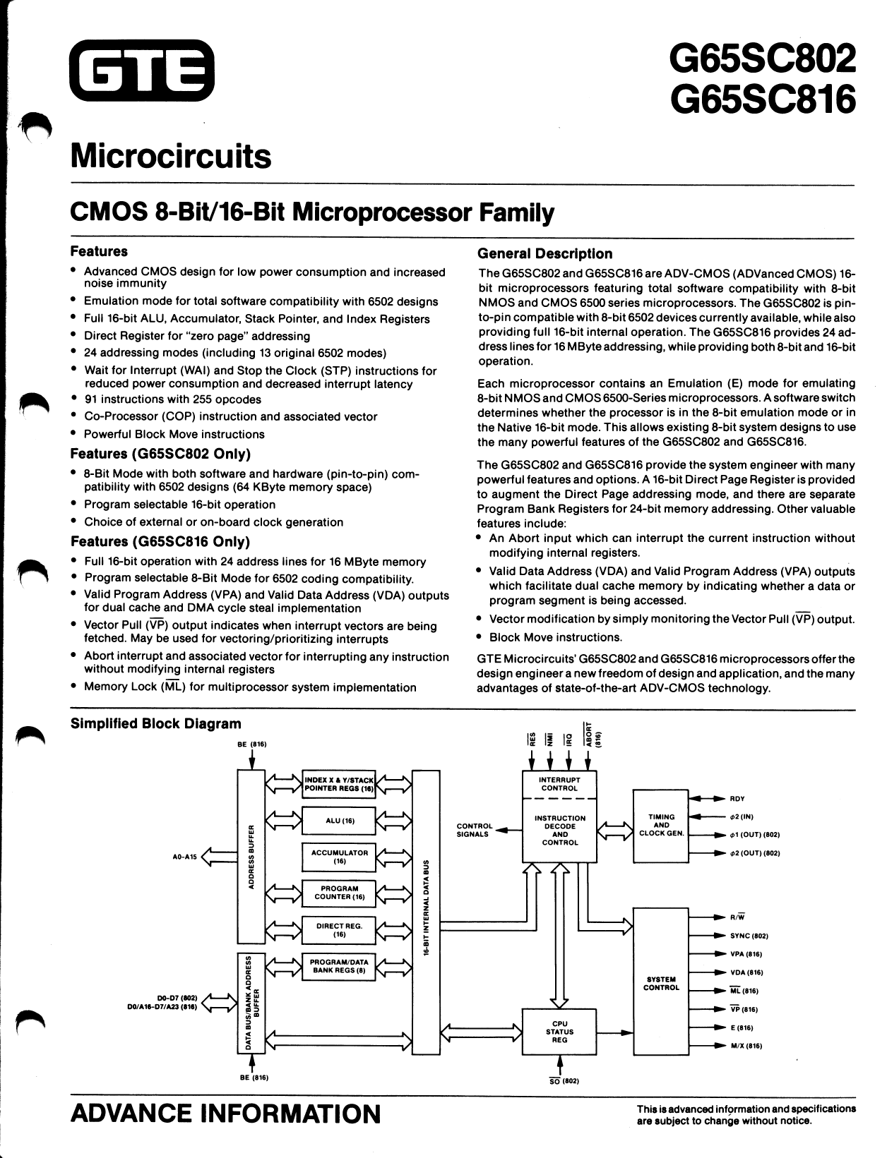
Simplified Block Diagram
l<2 •1
DO-D7 (802)
D0/A16-D7/A23 (816)
ADVANCE INFORMATION
This isadvanced information and specifications
are subject to change without notice.
1 page 
t
Index (X and Y)
There are two Index Registers (X and Y) which may be used as general
purpose registers or to provide an index value for calculation of the ef
fective address. When executing an instruction with indexed addressing,
the microprocessor fetches the opcode and the base address, and then
modifies the address by adding the Index Register contents to the ad
dress prior to performing the desired operation. Pre-indexing or post
indexing of indirect addresses may be selected. In the Native mode (E=0),
both Index Registers are 16 bits wide (providing the Index Select Bit (X)
equals zero). If the Index Select Bit (X) equals one, both registers will be
8 bits wide.
Processor Status (P)
The 8-bit Processor Status Register contains status flags and mode select
bits. The Carry (C), Negative (N), Overflow (V), and Zero (Z) status flags
serve to report the status of most ALU operations. These status flags are
tested by use of Conditional Branch instructions. The Decimal (D), IRQ
Disable (I), Memory/Accumulator (M), and Index (X) bits are used as
mode select flags. These flags are set by the program to change micro
processor operations.
The Emulation (E) select and the Break (B) flags are accessible only
through the Processor Status Register. The Emulation mode select flag
is selected by the Exchange Carry and Emulation Bits (XCE) instruction.
Table 2, G65SC802 and G65SC816 Mode Comparison, illustrates the
features of the Native (E=0) and Emulation (E=1) modes. The M and X
flags are always equal to one in the Emulation mode. When an interrupt
occurs during the Emulation mode, the Break flag is written to stack mem
ory as bit 4 of the Processor Status Register.
Program Bank (PB)
The 8-bit Program Bank Register holds the bank address for all instruc
tion fetches. The 24-bit address consists of the 16-bit instruction effective
address and the 8-bit Program Bank address. The register value is multi
plexed with the data value and presented on the Data/Address lines during
the first half of a program memory read cycle. The Program Bank Regis
ter is initialized to zero during Reset.
Program Counter (PC)
The 16-bit Program Counter Register provides the addresses which are
used to step the microprocessor through sequential program instruc
tions. The register is incremented each time an instruction or operand is
fetched from program memory.
Stack Pointer (S)
The Stack Pointer is a 16-bit register which is used to indicate the next
available location in the stack memory area. It serves as the effective ad
dress in stack addressing modes as well as subroutine and interrupt pro
cessing. The Stack Pointer allows simple implementation of nested sub
routines and multiple-level interrupts. During the Emulation mode, the
Stack Pointer high-order byte (SH) is always equal to one.
%
V dd
Vss
%
02 (IN)
01 (OUT) (802)
02 (OUT) (802)
R/W (802, 816)
SYNC (802)
VPA (816)
VDA (816)
ML (816)
VP (816)
E (816)
M/X (816)
5
5 Page 
Interrupt Processing Sequence
The interrupt processing sequence is initiated as the direct result of hard-
ware Abort, Interrupt Request, Non-Maskable Interrupt, or Reset inputs.
The interrupt sequence can also be initiated as a result of the Break or
Co-Processor instructions within the software. The following listings
describe the function of each cycle in the interrupt processing sequence:
Hardware Interrupt—ABORT, IRQ, NMI, RES Inputs
Cycici No.
E=0 E=1
Address
Data
R/W SYNC
11
22
3 [1]
43
54
65
76
87
PC
PC
s
s
s
s
VL
VH
X
X
PB
PCH [2]
PCL [2]
P [4]
(VL)
(VH)
1
1
0
o [3]
0 [3]
0 [3]
1
1
1
0
0
0
0
0
0
0
VDA
1
0
1
1
1
1
1
1
VPA
1
0
0
0
0
0
0
0
VP
1
1
1
1
1
1
0
0
Description
Internal Operation
Internal Operation
Write PB to Stack, S-1 — S
Write PCH to Stack, S-1 — S
Write PCL to Stack, S-1 —S
Write P to Stack, S-1 —S
Read Vector Low Byte, P: 0 — D, 1 - I
Read Vector High Byte
Software Interrupt—BRK, COP Instructions
CycU?No.
E =0 E=1
Address
Data
R/W
11
22
3 [1]
43
54
65
76
87
PC-2
PC-1
S
S
S
S
VL
VH
X
X
PB
PCH
PCL
P
(VL)
(VH)
1
1
0
0
0
0
1
1
SYNC
1
0
0
0
0
0
0
0
Notes:
[1] Delete this cycle in Emulation mode.
[2] Abort writes address of aborted opcode.
[3] R/W remains in the high state during Reset.
[4] In Emulation mode, bit 4 written to stack is changed to 0.
1
0
1
1
1
1
1
1
— Description
1 1 Opcode
1 1 Signature
0 1 Write PB to Stack, S-1 — S
0 1 Write PCH to Stack, S-1 - S
0 1 Write PCL to Stack, S-1 — S
0 1 Write P to Stack, S-1 —S
0 0 Read Vector Low Byte, P: 0 — D, 1 — I
0 0 Read Vector High Byte
Name
ABORT
BRK
COP
IRQ
NMI
RESET
Table 3. Vector Locations
Source
Hardware
Software
Software
Hardware
Hardware
Hardware
Emulation
(E = 1)
00FFF8.9
OOFFFE.F
00FFF4.5
OOFFFE.F
OOFFFA.B
OOFFFC.D
Native
(E = 0)
00FFE8.9
00FFE6.7
00FFE4,5
OOFFEE.F
OOFFEA.B
OOFFFC.D
(1-E )
11 Page | ||
| Páginas | Total 20 Páginas | |
| PDF Descargar | [ Datasheet G65SC816.PDF ] | |
Hoja de datos destacado
| Número de pieza | Descripción | Fabricantes |
| G65SC816 | CMOS 8/16-BIT MICROPROCESSOR | California Micro Devices Corp |
| Número de pieza | Descripción | Fabricantes |
| SLA6805M | High Voltage 3 phase Motor Driver IC. |
Sanken |
| SDC1742 | 12- and 14-Bit Hybrid Synchro / Resolver-to-Digital Converters. |
Analog Devices |
|
DataSheet.es es una pagina web que funciona como un repositorio de manuales o hoja de datos de muchos de los productos más populares, |
| DataSheet.es | 2020 | Privacy Policy | Contacto | Buscar |