|
|
|
PDF VS-GA250SA60S Data sheet ( Hoja de datos )
| Número de pieza | VS-GA250SA60S | |
| Descripción | Insulated Gate Bipolar Transistor | |
| Fabricantes | Vishay | |
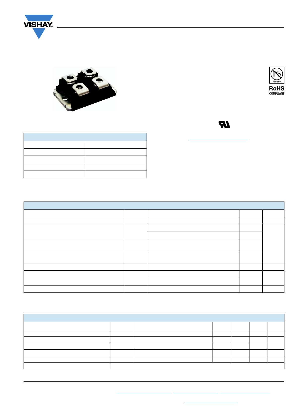
| Logotipo | ||
Hay una vista previa y un enlace de descarga de VS-GA250SA60S (archivo pdf) en la parte inferior de esta página. Total 9 Páginas | ||
|
No Preview Available !
www.vishay.com
VS-GA250SA60S
Vishay Semiconductors
Insulated Gate Bipolar Transistor
Ultralow VCE(on), 250 A
SOT-227
PRODUCT SUMMARY
VCES
VCE(on) (typical) at 200 A, 25 °C
IC at TC = 90 °C (1)
Package
600 V
1.33 V
250 A
SOT-227
Circuit
Single Switch no Diode
Note
(1) Maximum collector current admitted 100 A to do not exceed the
maximum temperature of terminals
FEATURES
• Standard: Optimized for minimum saturation
voltage and low speed up to 5 kHz
• Lowest conduction losses available
• Fully isolated package (2500 VAC)
• Very low internal inductance (5 nH typical)
• Industry standard outline
• Designed and qualified for industrial level
• UL approved file E78996
• Material categorization: For definitions of compliance
please see www.vishay.com/doc?99912
BENEFITS
• Designed for increased operating efficiency in power
conversion: UPS, SMPS, TIG welding, induction heating
• Easy to assemble and parallel
• Direct mounting to heatsink
• Plug-in compatible with other SOT-227 packages
ABSOLUTE MAXIMUM RATINGS
PARAMETER
SYMBOL
TEST CONDITIONS
Collector to emitter voltage
VCES
Continuous collector current
Pulsed collector current
Clamped Inductive load current
Gate to emitter voltage
IC (1)
TC = 25 °C
TC = 90 °C
ICM
Repetitive rating; VGE = 20 V, pulse width limited
by maximum junction temperature
ILM
VCC = 80 % (VCES), VGE = 20 V,
L = 10 μH, Rg = 2.0 ,
VGE
Power dissipation
TC = 25 °C
PD
TC = 90 °C
Isolation voltage
VISOL
Any terminal to case, t = 1 minute
Note
(1) Maximum collector current admitted 100 A to do not exceed the maximum temperature of terminals
MAX.
600
400
250
400
400
± 20
961
462
2500
UNITS
V
A
V
W
V
THERMAL AND MECHANICAL SPECIFICATIONS
PARAMETER
SYMBOL
Junction and storage temperature range
Thermal resistance junction to case
Thermal resistance case to heatsink
Weight
Mounting torque
Case style
TJ, TStg
RthJC
RthCS
Flat, greased surface
SOT-227
MIN.
-40
-
-
-
-
TYP.
-
-
0.05
30
-
MAX.
150
0.13
-
-
1.3
UNITS
°C
°C/W
g
Nm
Revision: 13-Sep-13
1 Document Number: 94704
For technical questions within your region: [email protected], [email protected], [email protected]
THIS DOCUMENT IS SUBJECT TO CHANGE WITHOUT NOTICE. THE PRODUCTS DESCRIBED HEREIN AND THIS DOCUMENT
ARE SUBJECT TO SPECIFIC DISCLAIMERS, SET FORTH AT www.vishay.com/doc?91000
1 page 
www.vishay.com
VS-GA250SA60S
Vishay Semiconductors
250
200
150
Square wave:
60 % of rated
100 voltage
I
50
Ideal diodes
For both:
Triangular wave:
Duty cycle: 50 %
I
TJ = 125 °C
Tsink = 90 °C
Gate drive as specified
Power dissipation = 140 W
Clamp voltage:
80 % of rated
0
0.1
1
10 100
f - Frequency (kHz)
Fig. 12 - Typical Load Current vs. Frequency (Load Current = IRMS of Fundamental)
30 000
24 000
18 000
12 000
VGE = 0 V, f = 1 MHz
Cies = Cge + Cgc, Cce shorted
Cres = Cgc
Coes = Cce + Cgc
Cies
Coes
6000
0
1
Cres
10
100
VCE - Collector to Emitter Voltage (V)
Fig. 13 - Typical Capacitance vs.
Collector to Emitter Voltage
20
VCC = 400 V
IC = 100 A
16
12
8
4
0
0 200 400 600 800
QG - Total Gate Charge (nC)
Fig. 14 - Typical Gate Charge vs.
Gate to Emitter Voltage
1000
VGE = 20 V
100 TJ = 125 °C
10
Safe operating area
1
1 10
100
1000
VCE - Collector to Emitter Voltage (V)
Fig. 15 - Turn-Off SOA
Revision: 13-Sep-13
5 Document Number: 94704
For technical questions within your region: [email protected], [email protected], [email protected]
THIS DOCUMENT IS SUBJECT TO CHANGE WITHOUT NOTICE. THE PRODUCTS DESCRIBED HEREIN AND THIS DOCUMENT
ARE SUBJECT TO SPECIFIC DISCLAIMERS, SET FORTH AT www.vishay.com/doc?91000
5 Page | ||
| Páginas | Total 9 Páginas | |
| PDF Descargar | [ Datasheet VS-GA250SA60S.PDF ] | |
Hoja de datos destacado
| Número de pieza | Descripción | Fabricantes |
| VS-GA250SA60S | Insulated Gate Bipolar Transistor | Vishay |
| Número de pieza | Descripción | Fabricantes |
| SLA6805M | High Voltage 3 phase Motor Driver IC. |
Sanken |
| SDC1742 | 12- and 14-Bit Hybrid Synchro / Resolver-to-Digital Converters. |
Analog Devices |
|
DataSheet.es es una pagina web que funciona como un repositorio de manuales o hoja de datos de muchos de los productos más populares, |
| DataSheet.es | 2020 | Privacy Policy | Contacto | Buscar |