|
|
|
PDF MAX3543 Data sheet ( Hoja de datos )
| Número de pieza | MAX3543 | |
| Descripción | Multiband Analog and Digital Television Tuner | |
| Fabricantes | Maxim Integrated | |
| Logotipo | ||
Hay una vista previa y un enlace de descarga de MAX3543 (archivo pdf) en la parte inferior de esta página. Total 20 Páginas | ||
|
No Preview Available !
19-4985; Rev 2; 7/10
EVAALVUAAILTAIOBNLEKIT
Multiband Analog and
Digital Television Tuner
General Description
The MAX3543 hybrid broadband single-conversion tele-
vision tuner is designed for use in analog (PAL, SECAM)
+ digital (DVB-T, GB20600) television sets and terrestrial
receivers. It receives all television bands from 47MHz
to 862MHz and converts the selected channel to an
industry-standard 36MHz IF.
The MAX3543 includes a variable-gain low-noise input
amplifier; an RF tracking filter; an image rejection mixer;
a peak detector; an optional internal, self-contained
RF gain-control loop (RFAGC); a VCO with fractional-N
PLL; an IF bandpass filter; an IF variable-gain amplifier;
separate analog and digital IF outputs; and a crystal
oscillator.
The MAX3543 is available in a small, 6mm x 6mm, thin QFN
package, and the application circuit fits in 20mm x 25mm on
a two-layer board with single-sided component mounting.
DVB-T/DVB-T2 +
PAL/SECAM
DVB-C + PAL/SECAM
Applications
DTMB/GB20600 + PAL
ATSC + NTSC
Features
S Standard IF Architecture Ensures < -70dBc Spurs
S Integrated RF Tracking Filter
S Integrated IF Bandpass Filter
S Full-Band Coverage (47MHz to 862MHz)
S 70dB Image Rejection
S 4dB Noise Figure
S Fast-Locking, Low Phase-Noise PLL Supports
256QAM
S Crystal Oscillator and Buffer/Divider to Drive
Baseband IC
S 745mW Power Dissipation
Ordering Information
PART
MAX3543CTL+
TEMP RANGE
0NC to +70NC
PIN-PACKAGE
40 TQFN-EP*
+Denotes a lead(Pb)-free/RoHS-compliant package.
*EP = Exposed paddle.
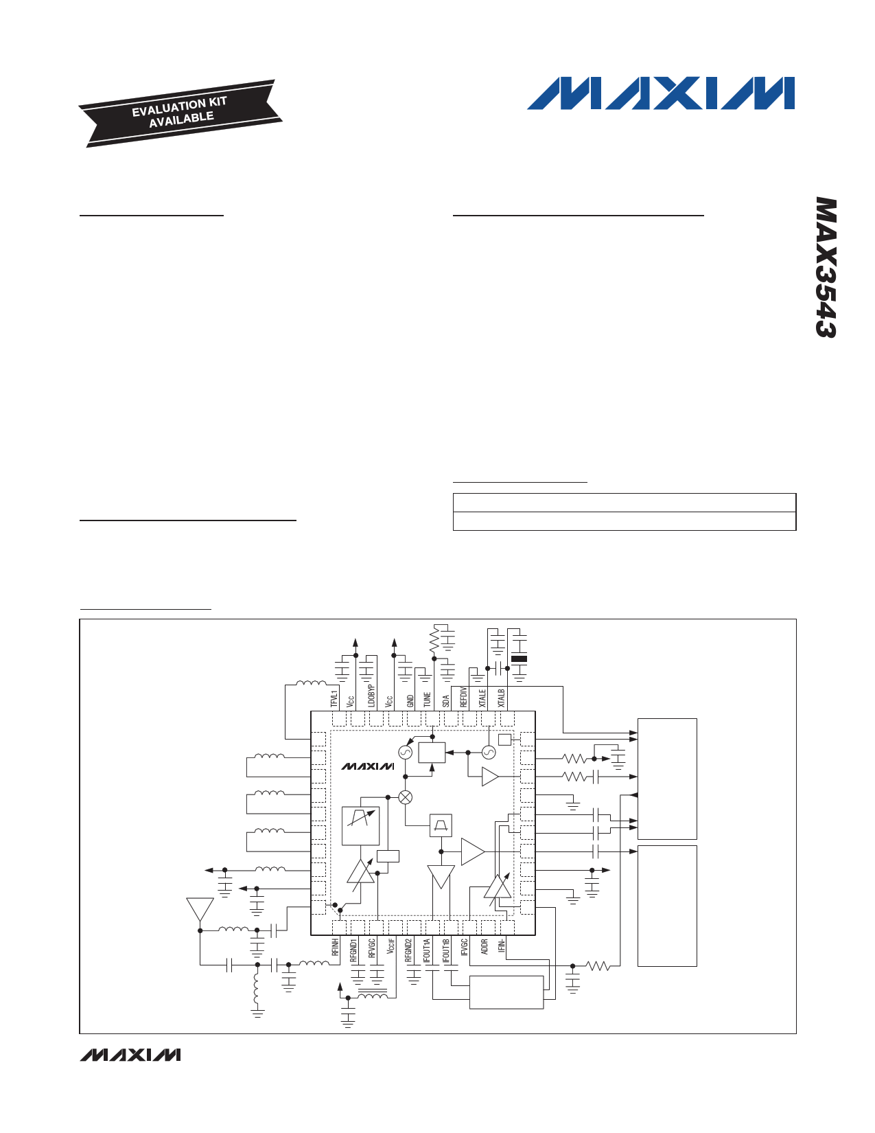
Block Diagram/Typical Application Circuit/Pin Configuration
30 29 28 27
TFVL2 31
TFVH1 32
TFVH2 33
TFU1 34
MAX3543
TFU2A 35
TFU2B 36
TFU3 37
LEXT 38
TRACKING
FILTER
PDET
VCC 39
RFINL 40
+
12 34
26 25 24
FRAC-N
PLL
567
23 22 21
I2C
/N
8 9 10
20 SCL
19 VCCDIG
18 REFOUT
17 GND
16 DTVOUT+
15 DTVOUT-
14 IFOUT2
13 VCC
12 GND
11 IFIN+
REF_OUT
I2C
DIGITAL
DEMODULATOR
OR
A+D
DEMODULATOR
IFVGC
DIG_IF
ANA_IF
ANALOG
DEMODULATOR
LC BANDPASS
FILTER
NOTE: LAYOUT FITS 25mm x 20mm ON 2-LAYER BOARD WITH DEVICE PLACEMENT ON TOP SIDE ONLY.
________________________________________________________________ Maxim Integrated Products 1
For pricing, delivery, and ordering information, please contact Maxim Direct at 1-888-629-4642,
or visit Maxim’s website at www.maxim-ic.com.
1 page 
Multiband Analog and
Digital Television Tuner
Typical Operating Characteristics
(MAX3543 Evaluation Kit, VCC = 3.3V, TA = +25NC, registers set according to Table 1, unless otherwise noted.)
CASCADED DTV VOLTAGE GAIN
vs. FREQUENCY
100
95 0°C
90
85
80 +25°C
+70°C
75
70
65
60
0
DVB-T MODE
100 200 300 400 500 600 700 800 900
FREQUENCY (MHz)
CASCADED DTV VOLTAGE GAIN
vs. IFVGC VOLTAGE
100
fRF = 666MHz
90
0°C
80
+25°C
70
60 +70°C
50
40
30
0.5
DVB-T MODE
1.0 1.5 2.0 2.5
IFVGC VOLTAGE (V)
3.0
ATV VOLTAGE GAIN
vs. RFVGC VOLTAGE
60
fRF = 666MHz
50
40 0°C
30
+25°C
20
10
+70°C
0
-10
-20
0.5
ATV MODE
1.0 1.5 2.0 2.5
RFVGC VOLTAGE (V)
3.0
CASCADED DTV VOLTAGE GAIN
vs. RFVGC VOLTAGE
100
fRF = 666MHz
90
80 0°C
70
+25°C
60
50
+70°C
40
30
20
0.5
DVB-T MODE
1.0 1.5 2.0 2.5
RFVGC VOLTAGE (V)
3.0
ATV VOLTAGE GAIN
vs. FREQUENCY
60
55
+25°C
0°C
50
45
40
+70°C
35
30
25
20
0
ATV MODE
100 200 300 400 500 600 700 800 900
FREQUENCY (MHz)
NOISE FIGURE
vs. FREQUENCY
10
9
INPUT DIPLEXER CROSSOVER
FREQUENCY IS 345MHz
8
7
6
+25°C
5
4
3
2
1
ATV MODE
0
0 100 200 300 400 500 600 700 800 900
FREQUENCY (MHz)
_______________________________________________________________________________________ 5
5 Page 
Multiband Analog and
Digital Television Tuner
Register and Bit Descriptions
Table 4. R00: VCO Register—VCO and LO Divider Control (Address: 00h)
BIT NAME
BIT LOCATION
(0 = LSB)
TYPICAL
SETTING
FUNCTION
VCO[1:0]
7:6
VCO select. Selects one of three VCOs when VAS = 0, or selects the VCO starting
band when VASS = 0.
01
00 = Selects VCO1 (approximately 2200MHz to 2800MHz)
01 = Selects VCO2 (approximately 2800MHz to 3500MHz)
10 = Selects VCO3 (approximately 3500MHz to 4400MHz)
11 = VCO shutdown
VSUB[3:0]
5:2
0011
VCO sub-band select. Selects one of 16 possible VCO sub-bands when VAS = 0,
or selects the VCO starting sub-band when VASS = 0.
0000 = Selects SB0
…
1111 = Selects SB15
VDIV[1:0]
1:0
VCO divider ratio select.
00 = Sets VCO divider to 4 (use when fLO > 550MHz)
00 01 = Sets VCO divider to 8 (use when 275MHz < fLO < 550MHz)
10 = Sets VCO divider to 16 (use when 137.5MHz < fLO < 275MHz)
11 = Sets VCO divider to 32 (use when fLO < 137.5MHz)
Table 5. R01: NDIV INT Register—Integer Part of N-Divider (Address: 01h)
BIT NAME
BIT LOCATION
(0 = LSB)
TYPICAL
SETTING
FUNCTION
NINT[7:0]
7:0
0010
1011
Sets the PLL integer divide number (N)
Table 6. R02: NDIV FRAC2 Register—N-Divider Fractional Part [19:16] and R-Divider
(Address: 02h)
BIT
NAME
CPS
CP
RDIV[1:0]
F[19:16]
BIT LOCATION
(0 = LSB)
7
6
5:4
3:0
TYPICAL
SETTING
1
0
00
1110
FUNCTION
Sets the charge-pump current-selection mode between automatic and manual.
Must set to 1 for proper operation.
For Maxim use only
Reference divider.
00 = /1
01 = /2
1X = Maxim use only
N-divider fractional part bits 19:16 (out of 19:0)
______________________________________________________________________________________ 11
11 Page | ||
| Páginas | Total 20 Páginas | |
| PDF Descargar | [ Datasheet MAX3543.PDF ] | |
Hoja de datos destacado
| Número de pieza | Descripción | Fabricantes |
| MAX354 | Fault-Protected Analog Multiplexers | Maxim Integrated |
| MAX3540 | Complete Single-Conversion Television Tuner | Maxim Integrated Products |
| MAX3541 | Complete Single-Conversion Television Tuner | Maxim Integrated Products |
| MAX3542 | Complete Single-Conversion Television Tuner | Maxim Integrated Products |
| Número de pieza | Descripción | Fabricantes |
| SLA6805M | High Voltage 3 phase Motor Driver IC. |
Sanken |
| SDC1742 | 12- and 14-Bit Hybrid Synchro / Resolver-to-Digital Converters. |
Analog Devices |
|
DataSheet.es es una pagina web que funciona como un repositorio de manuales o hoja de datos de muchos de los productos más populares, |
| DataSheet.es | 2020 | Privacy Policy | Contacto | Buscar |