|
|
|
PDF XC9140 Data sheet ( Hoja de datos )
| Número de pieza | XC9140 | |
| Descripción | Step-UpSynchronous PFM DC/DC Converter | |
| Fabricantes | TOREX | |
| Logotipo | ||
Hay una vista previa y un enlace de descarga de XC9140 (archivo pdf) en la parte inferior de esta página. Total 28 Páginas | ||
|
No Preview Available !
XC9140 Series
Step-Up Synchronous PFM DC/DC Converter
ETR04015-003
■ GENERAL DESCRIPTION
☆GreenOperation Compatible
The XC9140 series are step-up synchronous DC/DC converters that support ceramic capacitors and have an internal 0.6Ω
(TYP.) Nch driver transistor and an internal 0.65Ω (TYP.) Pch synchronous rectifier switch transistor. PFM control enables a low
quiescent current, making these products ideal for portable devices that require high efficiency.
When the output voltage is 3.3V and the load current is 1mA (XC9140Axx1 type and XC9140Cxx1 type), startup from an input
voltage of VIN = 0.9V is possible which means that these products can be used in applications that start using a single alkaline or
nickel-metal hydride battery. The output voltage can be set from 1.8V to 5.0V (±2.0%) in steps of 0.1V.
The XC9140 features a load disconnect function to break continuity between the input and output at shutdown (XC9140A), and
also a bypass mode function to maintain continuity between the input and output (XC9140C).
A version with a UVLO (Under Voltage Lock-out) function is also available. This function enables the prevention of battery leakage
by stopping IC’s operation when the input voltage is low. The standard product has a UVLO release voltage of 2.15V (±3.0%), and a
custom version with a release voltage selectable from between 1.65V to 2.2V, in steps of 0.05V, is also available.
■APPLICATIONS
● Mouses, Keyboards
● Bluetooths
● Household use Medical equipments
● Remote controls
● Game consoles
● Devices with 1~3 Alkaline, 1~3 Nickel Hydride,
1 Lithium and 1 Li-ion
■FEATURES
Input Voltage Range
Output Voltage Setting
Output Current
Driver Transistor
Supply Current
Control Method
High speed transient response
PFM Switching Current
Functions
Operating Ambient Temperature
Packages
Environmentally Friendly
: 0.9V~5.5V
: 1.8V~5.0V (±2.0%) 0.1V increments
: 100mA@VOUT=3.3V, VBAT=1.8V (TYP.)
: 0.6Ω Nch driver transistor
0.65Ω Pch synchronous rectifier switch transistor
: 6.3μA (VBAT=VOUT+0.5V)
: PFM Control
: 50mV@VOUT=3.3V, VBAT=1.8V, IOUT=1→50mA
: 350mA
: Load Disconnection Function or
Bypass Mode Function
UVLO Function
Ceramic Capacitor
: -40℃~+85℃
: SOT-25, USP-6EL
: EU RoHS Compliant, Pb Free
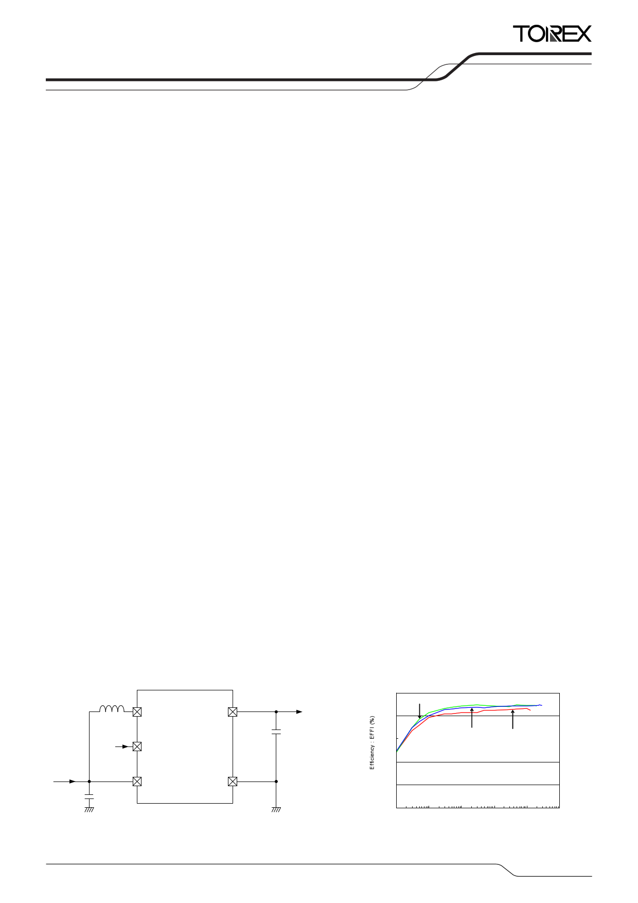
■TYPICAL APPLICATION CIRCUIT
L=4.7μH
LX
CE
VIN=0.9~5.5V
CCIN=IN1=04.μ7μFF
VBAT
VOUT
GND
CL=10μF
■TYPICAL PERFORMANCE
CHARACTERISTICS
●Efficiency vs. Output Current
XC9140A331MR-G(VOUT=3.3V)
L=4.7μH(VLF302512M-4R7M),CIN=4.7μF(LMK107BJ475MA),
100 CL=10μF(LMK107BJ106MA)
2.5V
80
60
3.0V
VBAT=1.8V
40
20
0
0.01
0.1 1
10 100
Output Current : IOUT (mA)
1000
1/28
1 page 
XC9140 (Design Target)
XC9140
Series
■ELECTRICAL CHARACTERISTICS (Continued)
●XC9140Cxx1 Type, without UVLO function, without CL discharge function
PARAMETER
SYMBOL
CONDITIONS
MIN.
TYP.
MAX.
Ta=25˚C
UNITS CIRCUIT
Input Voltage
Output Voltage
Operation Start Voltage
Operation Hold Voltage
Supply Current
Input Pin Current
Bypass Mode Current
VBAT
V (*2)
OUT(E)
VST1
VHLD
Iq
IBAT
IBYP
VPULL=1.5V, Voltage to start oscillation
while VOUT is decreasing
IOUT=1mA
RL=1kΩ
Oscillation stops,
VOUT=VOUT(T)+0.5V (*1)
VOUT=VOUT(T)+0.5V (*1)
VBAT=VLX=5.5V, VCE=0V
-
- 5.5 V
-
E1 V ①
- - 0.9 V ②
- 0.7 - V ②
E2 μA ③
-
0.25 1.0 μA
③
- 3.5 6.1 μA ⑥
PFM Switching Current
IPFM IOUT=3mA
295 350 405 mA
②
Maximum ON Time
Efficiency (*3)
Efficiency (*3)
Efficiency (*3)
LX SW “Pch” ON
Resistance (*4)
LX SW “Nch” ON
Resistance (*5)
tONMAX
EFFI
EFFI
EFFI
RLXP
RLXN
VPULL=1.5V, VOUT=VOUT(T)×0.98V (*1)
VBAT=VCE=1.8V, VOUT(T) (*1)=2.5V,
IOUT=30mA
VBAT=VCE=1.8V, VOUT(T) (*1)=3.3V,
IOUT=30mA
VBAT=VCE=1.8V, VOUT(T) (*1)=5.0V,
IOUT=30mA
VBAT=VLX=VCE= VOUT(T)+0.5V (*1),
IOUT=200mA
VBAT=VCE=3.3V, VOUT=1.7V
3.1 4.6 6.0 μs
- 81 - %
- 85 - %
- 86 - %
E3 Ω
- 0.6 - Ω
CE “High” Voltage
VCEH
VBAT=VPULL=1.5V,
VOUT=VOUT(T)×0.98V (*1)
While VCE=0.3→0.75V,
Voltage to start oscillation
0.75 - 5.5 V
CE “Low” Voltage
VCEL
VBAT=VPULL=1.5V,
VOUT=VOUT(T)×0.98V (*1)
While VCE=0.75→0.3V,
Voltage to stop oscillation
GND
-
0.3 V
CE “High” Current
ICEH VBAT=VCE=VLX=VOUT=5.5V
-0.1 - 0.1 μA
CE “Low” Current
ICEL VBAT=VLX=VOUT=5.5V, VCE=0V
-0.1 - 0.1 μA
Unless otherwise stated, VBAT=VCE=1.5V
(*1) VOUT(T)=Nominal Output Voltage
(*2) VOUT(E)=Effective Output Voltage
The actual output voltage value VOUT(E) is the PFM comparator threshold voltage in the IC.
Therefore, the DC/DC circuit output voltage, including the peripheral components, is boosted by the ripple voltage average value.
Please refer to the characteristic example.
(*3) EFFI={[(Output Voltage)×(Output Current)] / [(Input Voltage)×(Input Current)]}×100
(*4) LX SW “Pch” ON resistance=(VLX-VOUT pin measurement voltage) / 200mA
(*5) The LX SW “Nch” ON resistance measurement method is shown in the measurement circuit diagram.
①
②
②
②
⑦
⑧
①
①
①
①
5/28
5 Page 
XC9140 (Design Target)
■TYPICAL APPLICATION CIRCUIT
XC9140
Series
【Reference External Components】
MANUFACTURE PRODUCT NUMBER
L
TDK
VLF302512M-4R7
CIN TAIYO YUDEN LMK107BJ475MA
CL TAIYO YUDEN LMK107BJ106MA
VALUE
4.7μH
4.7μF/10V
10μF/10V
* When selecting components, take into consideration capacitance reduction, voltage, etc.
* The characteristics are dependent on the variation in the coil inductance value, so check these carefully in the actual product.
* A coil inductance value of 4.7 to 10.0μH can be used, but using 4.7μH is recommended.
* The ripple voltage will increase if tantalum or electrolytic capacitors are used for the load capacitor CL. The operation could also become
unstable, so carefully check this in the actual product.
11/28
11 Page | ||
| Páginas | Total 28 Páginas | |
| PDF Descargar | [ Datasheet XC9140.PDF ] | |
Hoja de datos destacado
| Número de pieza | Descripción | Fabricantes |
| XC9140 | Step-UpSynchronous PFM DC/DC Converter | TOREX |
| XC9141 | 0.8A Step-up DC/DC Converters | Torex Semiconductor |
| XC9142 | 0.8A Step-up DC/DC Converters | Torex Semiconductor |
| XC9144-10PQ100C | XC95144 In-System Programmable CPLD | Xilinx |
| Número de pieza | Descripción | Fabricantes |
| SLA6805M | High Voltage 3 phase Motor Driver IC. |
Sanken |
| SDC1742 | 12- and 14-Bit Hybrid Synchro / Resolver-to-Digital Converters. |
Analog Devices |
|
DataSheet.es es una pagina web que funciona como un repositorio de manuales o hoja de datos de muchos de los productos más populares, |
| DataSheet.es | 2020 | Privacy Policy | Contacto | Buscar |