|
|
|
PDF DG502AP Data sheet ( Hoja de datos )
| Número de pieza | DG502AP | |
| Descripción | 2-DOOR CONTROLLER | |
| Fabricantes | CDVI | |
| Logotipo | ||
Hay una vista previa y un enlace de descarga de DG502AP (archivo pdf) en la parte inferior de esta página. Total 9 Páginas | ||
|
No Preview Available !
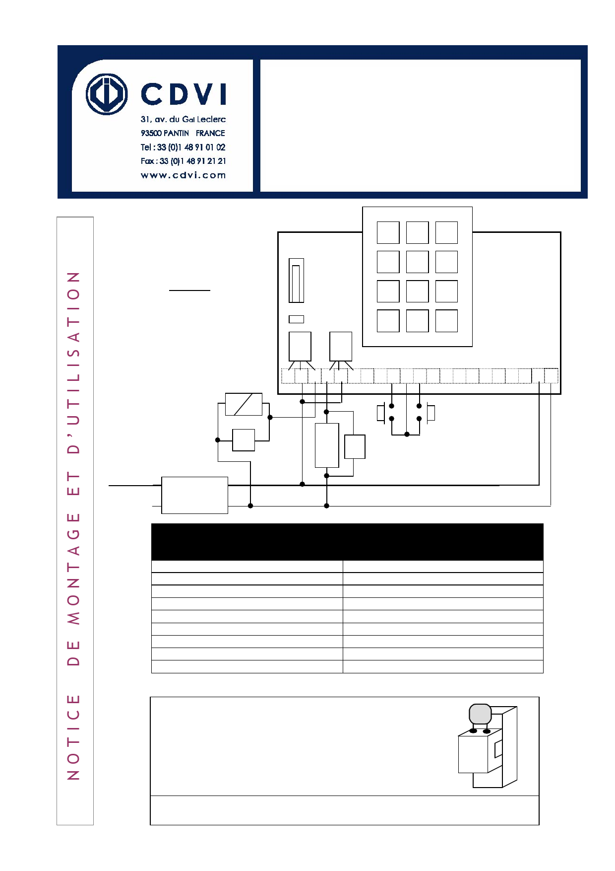
Edition 12/2005
DG502U/A
DG502U/P
2-DOOR CONTROLLER
500 USERS
123
Warning
Do not use a switching power
supply because of the interference
radiation that may disturb the
reading of the badges
Ne pas utiliser d’alimentation
à découpage à
rayonnements
cause de
parasites
posutvriaknet
perturber la lecture des badges.
456
1…2 3
ST1
RL1
RL2
789
0 #
R C T R C T S S B M E 1 2 3 4 5 6 12 V 12 V
PB1
V1
Input voltage
12VAC/DC
M
A
G V2
N
E
T
PB2
Terminal
B
E
M
R
C
T
V1,V2
ST1
S,S
Description
Request-to-Exit input 1
Request-to-Exit input 2
Common REX inputs
N/C Contact door
Common
N/O Contact door
Varistor
Jumper for reset
Tamper Switch output
This device comes with a varistor.
The varistor must be connected to the strike terminal
(electromagnet…) operated by the device.
If this product works with many strikes, each of them
should have a varistor.
The varistor controls the overload produced by the strike
coil – self-effect.
If you are using a « Shear Lock » electromagnetic lock, it is recommended to
use a separate power supply than the one connected to the DG502U!
1 page 
Edition 12/2005
Note: the time outputs and the enrolment reader are not set to their default settings.
Relay Outputs
Badge 1 – Access Level 01
Badge 2 – Access Level 02
relays
Badge 3 – Access Level 03
Controller built-in reader activates relay 1
Remote reader 1 activates relay 1
Controller built-in reader activates no
Remote reader 2 activates relay 2
Controller built-in reader activates relay 1
Remote reader 1 activates relay 1
Remote reader 2 activates relay 2
Reset to Factory Default Values
Cut the power on the DG502 unit
Place the jumper on ST1, 2-3 position
Power on the DG502, the LED is still off
Remove the jumper from ST1, 2-3 position, the LED flashes orange
Wiring of the Remote Readers
Follow the schematic on page 1 to connect remote reader 1 to the controller. Connect terminals 2, 3, 4,
5, 12 and V from the controller directly to the terminals on the remote reader 1. Terminal 6 on the
controller is connected to terminal 1 of remote reader 1.
For remote reader 2, connect in parallel terminals 2, 3, 4, 5, 12 and V from the controller unit. Terminal 1
on the controller is connected to terminal 1 of remote reader 2.
To power the remote readers use a different power supply or use the 12V output from the
controller (At the right hand completely it is the inputs 12V of the controller. The 12V at
the left of the other 12V is the output).
5
5 Page | ||
| Páginas | Total 9 Páginas | |
| PDF Descargar | [ Datasheet DG502AP.PDF ] | |
Hoja de datos destacado
| Número de pieza | Descripción | Fabricantes |
| DG502AP | 2-DOOR CONTROLLER | CDVI |
| Número de pieza | Descripción | Fabricantes |
| SLA6805M | High Voltage 3 phase Motor Driver IC. |
Sanken |
| SDC1742 | 12- and 14-Bit Hybrid Synchro / Resolver-to-Digital Converters. |
Analog Devices |
|
DataSheet.es es una pagina web que funciona como un repositorio de manuales o hoja de datos de muchos de los productos más populares, |
| DataSheet.es | 2020 | Privacy Policy | Contacto | Buscar |