|
|
|
PDF HBCR-2297 Data sheet ( Hoja de datos )
| Número de pieza | HBCR-2297 | |
| Descripción | Programmable Bar Code Decode ICs | |
| Fabricantes | Agilent(Hewlett-Packard) | |
| Logotipo | ||
Hay una vista previa y un enlace de descarga de HBCR-2297 (archivo pdf) en la parte inferior de esta página. Total 15 Páginas | ||
|
No Preview Available !
H
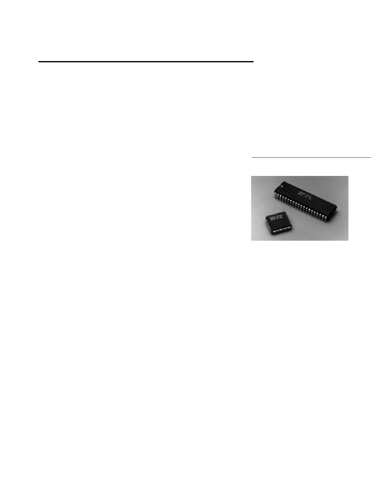
Programmable
Bar Code Decode ICs
Technical Data
HBCR-2210
HBCR-2211
Features
• Ideal for Hand Scanning and
Non-contact Laser Scanning
Applications
• Supports 7 Industry
Standard Bar Code
Symbologies
• Automatic Code Recognition
• Choice of Parallel or Serial
Interface
• Full Duplex ASCII Interface
• Extensive Configuration
Control
• Optical and Escape
Sequence Configuration
• Input and Output Buffering
• Low Current (18 mA) CMOS
Technology
• 40 Pin DIP and 44 Pin PLCC
Packages
• Audio and Visual Feedback
Control
• EEPROM Support for
Nonvolatile Configuration
• Single +5 Volt Supply
Description
Hewlett-Packard’s Bar Code
Decoder ICs offer flexible bar
code decoding capability that is
designed to give OEMs the ability
to address a growing number of
industry segments and applica-
tions. Flexibility is made possible
through sophisticated firmware
which allows the ICs to accept
data from a wide variety of
scanners and to automatically
recognize and decode the most
popular bar code symbologies.
User implementation of the
decoder ICs is easy since it
requires only a few supporting
components and provides a
standard I/O interface.
Manufacturers of data collection
terminals, point of sale terminals,
keyboards, weighing scales,
medical equipment, test instru-
mentation, material handling
equipment, and other systems
having data collection needs are
finding a growing demand for bar
code reading capability in their
products. The HBCR-2210 series
decode ICs make it easy to add
this capability without the need to
invest in the development of bar
code decoding software.
The bar code decoder ICs are
compatible with most hand held
scanners and some medium
speed machine mounted laser
heads. The HBCR-2210 series is
compatible with fixed beam non-
contact scanners, digital wands,
and slot readers. In addition, the
decoder is optimized for use with
the Symbol Technologies moving
beam laser scanners, but is also
compatible with many other
moving beam non-contact laser
scanners with a similar interface
protocol.
The HBCR-2210 series decoder
ICs are excellent decoding solu
5965-5937E
4-47
1 page 
DC Characteristics
HBCR-2210, 2211
Symbol
Parameter
VIL Input Low Voltage
VIH Input High Voltage
VIH1
VOL
VOL1
VOH
Input High Voltage
Output Low Voltage
Output Low Voltage
Output High Voltage
VOH Output High Voltage
IIL
IIL2
ILI
RRST
ICC
ICC
Input Low Current
Input Low Current
Input Leakage Current
Pulldown Resistor
Power Supply
Current
Idle Mode Power
Supply Current
(TA = 40°C to +85°C, VCC = 4.5 V to 5.5 V, VSS = 0 V)
HBCR-2210 Pins HBCR-2211 Pins Min.
Max. Units Test Conditions
all
all
-0.5
0.2 VCC
V
- 0.1
except 9, 18
except 10, 20
0.2 VCC VCC + 0.5
+ 0.9
V
9, 18
1-8, 10-17, 21-28
30, 32-39
1-8, 10-17, 21-28
30, 32-39
1-8, 10-17, 21-28
18
32-39
9
10, 20
0.7 VCC
2-9, 11, 13-19, 24-31
33, 36-43
2-9, 11, 13-19, 24-31 2.4
33, 36-43
0.75 VCC
0.9 VCC
2.4
2-9, 11, 13-19, 24-31
0.75 VCC
0.9 VCC
-10
20
36-43
10 20
VCC + 0.5
0.45
0.45
-200
-3.2
± 10
125
V
V
V
V
V
V
V
V
V
µA
mA
µA
KΩ
IOL = 1.6 mA
IOL = 3.2 mA
IOH = -60 µA
IOH = -30 µA
IOH = -10 µA
IOH = -400 µA
IOH = -150 µA
IOH = -40 µA
VIN = 0.45 V
VIN = 0.45 V
0.45 ≤ VIN ≤ VCC
––
18 mA All Outputs
disconnected
––
9 mA Note 7.
Note:
7. Applies only to HBCR-2210 and -2211 in Wand Mode or Laser Mode with Laser Idling enabled with no scanning or I/O operation in
progress.
Table 2. Summary of Features and Configurations - HBCR-2210 Series
In the table below, the column entitled Selection is either:
Software
Hardwire
Both
Escape Sequence and Optical Menu Programmability
Control of a feature by electrically strapping specified pins on the decoder IC itself
Both Software and Hardwire
Feature
Code Selection
Minimum/Maximum
Label Length
Selection
Interleaved 2 of 5
Specific Label
Length Selection
Function or Value
When a symbology is enabled,
bar codes of that type can be
read, assuming that other de-
coding options are satisfied.
Code 39, Codabar, Code 128,
Code 11, and MSI Code
Interleaved 2 of 5
Length variable from 4 to 32,
or a specific even length be-
tween 2 and 32, or lengths 6
and 14 only
Selection
Both
Default Setting
Decoding of all
codes is enabled
Software
Software
Software
Min. = 1
Max. = 32
Min. = 4
Max. = 32
4 to 32
(continued)
4-51
5 Page 
PLCC Drying
Whenever Vapor Phase or Infra-
red Reflow Technologies are used
to mount the PLCC packages,
there is a possibility that
previously absorbed moisture,
heated very rapidly to the reflow
temperatures, may cause the
package to crack from the
internal stresses. There is a
reliability concern that moisture
may then enter the package over
a period of time, and metal
corrosion may take place,
degrading the IC performance.
To reduce the amount of
absorbed moisture and prevent
cracking, all of the PLCC ICs
should undergo one of the
following baking cycles. The
parts must then be mounted
within 48 hours.
Hewlett-Packard cannot guaran-
tee the performance and
reliability of the parts.
If the parts are not mounted with-
in 48 hours, they must be re-
baked.
The total number of baking cycles
must not exceed two. If the ICs
are baked more than twice,
Neither bake cycle can be per-
formed in the standard shipping
tubes. The ICs must be baked in
an ESD safe, mechanically stable
container, such as an aluminum
tube or pan.
Cycle Temperature
A 125°C
B 60°C
Time
24 hrs
96 hrs
Notes
8
Note:
8. Cycle B must be done in atmosphere of <5% relative
humidity air or nitrogen.
Pin Definitions
BR0
BR1
STB
CTS
RTS
LSE
SCT
TRG
RST
RxD
TxD
SDI
SSY
LED
BPR
WR
RD
XTAL 2
XTAL 1
VSS
1
2
3
4
5
6
7
8
9
10
11
12
13
14
15
16
17
18
19
20
40 VCC
39 AD0
38 AD1
37 AD2
36 AD3
35 AD4
34 AD5
33 AD6
32 AD7
31 EA + 5 V
30 ALE
29 NC
28 SMD + 5 V
27 EEP
26 EPC
25 ECE/PT1
24 EIO/PT0
23 A10
22 A9
21 A8
Figure 3. HBCR-2210 Serial Pinout.
AD0-AD7
RxD
TxD
BR0-BR1
PT0-PT1
STB
LSE
SCT
SDI
LED
BPR
WR
RD
XTAL1
XTAL2
SMD
RTS
CTS
RST
EEP
EPC
ECE
EIO
TRG
SSY
A8
A9
A10
EA
ALE
VCC
VSS
PIN MNEMONICS
ADDRESS/DATA BUS
RECEIVED DATA
TRANSMITTED DATA
BAUD RATE
PARITY
STOP BITS
LASER SCAN ENABLE
SCANNER TYPE
SCANNER DIGITAL INPUT
LED CONTROL LINE
BEEPER CONTROL LINE
DATA MEMORY WRITE
DATA MEMORY READ
CRYSTAL INPUT
CRYSTAL INPUT
SERIAL MODE SELECT
REQUEST TO SEND
CLEAR TO SEND
IC RESET
EEPROM SELECT
EEPROM CLOCK
EEPROM CHIP ENABLE
EEPROM I/O
LASER TRIGGER LINE
SCANNER SYNCHRONIZATION
ADDRESS LINE #8
ADDRESS LINE #9
ADDRESS LINE #10
EXTERNAL PROGRAM ENABLE
ADDRESS LATCH ENABLE
POWER
GROUND
4-57
11 Page | ||
| Páginas | Total 15 Páginas | |
| PDF Descargar | [ Datasheet HBCR-2297.PDF ] | |
Hoja de datos destacado
| Número de pieza | Descripción | Fabricantes |
| HBCR-2297 | Programmable Bar Code Decode ICs | Agilent(Hewlett-Packard) |
| Número de pieza | Descripción | Fabricantes |
| SLA6805M | High Voltage 3 phase Motor Driver IC. |
Sanken |
| SDC1742 | 12- and 14-Bit Hybrid Synchro / Resolver-to-Digital Converters. |
Analog Devices |
|
DataSheet.es es una pagina web que funciona como un repositorio de manuales o hoja de datos de muchos de los productos más populares, |
| DataSheet.es | 2020 | Privacy Policy | Contacto | Buscar |