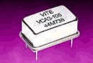
|
|
PDF VCA3 Data sheet ( Hoja de datos )
| Número de pieza | VCA3 | |
| Descripción | CMOS Crystal Oscillator | |
| Fabricantes | Vectron | |
| Logotipo |  |
|
 1. - Crystal Oscillator - Vectron Hay una vista previa y un enlace de descarga de VCA3 (archivo pdf) en la parte inferior de esta página. Total 6 Páginas | ||
|
No Preview Available !
VCA3 series
3.3, 5.0 volt CMOS Oscillator
The VCA3 Crystal Oscillator
Output
Buffer /
Disable
Features
• CMOS output
• Output frequencies to 160 MHz
• Tri-state output for board test and debug
• 0/70 or –40/85 °C operating temperature
• Product is compliant to RoHS directive
and fully compatible with lead free assembly
Applications
• SONET/SDH/DWDM
• Ethernet, Gigabit Ethernet
• Storage Area Network
• Digital Video
• Broadband Access
fo • Microprocessors/DSP/FPGA
Description
Vectron’s VCA3 Crystal Oscillator (XO) is quartz
stabilized square wave generator with a CMOS
output, operating off a 3.3 or 5.0 volt supply.
The VCA3 uses fundamental or 3rd overtone
crystals, for output frequencies < 80MHz,
resulting in low jitter performance, typically 0.5ps
rms in the 12 kHz to 20MHz band.
Vectron International 267 Lowell Road, Hudson NH 03051 Tel: 1-88-VECTRON-1 e-mail: [email protected]
1 page 
VCA3 Data Sheet
Reliability
The VCA3 qualification tests have included:
Table 4. Environnemental Compliance
Param e t e r
Mechanical Shock
Mechanical Vibration
Temperature Cycle
Gross and Fine Leak
Resistance to Solvents
Conditions
MIL-STD-883 Method 2022
MIL-STD-883 Method 2007
MIL-STD-883 Method 1010
MIL-STD-883 Method 1014
MIL-STD-883 Method 2015
Handling Precautions
Although ESD protection circuitry has been designed into the the VCA3, proper precautions should be taken
when handling and mounting. VI employs a Human Body Model and a Charged-Device Model (CDM) for
ESD susceptibility testing and design protection evaluation. ESD thresholds are dependent on the circuit
parameters used to define the model. Although no industry wide standard has been adopted for the CDM, a
standard HBM of resistance = 1.5kohms and capacitance = 100pF is widely used and therefore can be
used for comparison purposes.
Table 5. ESD Ratings
Model
Human Body Model
Charged Device Model
Minimum
1000
1500
Conditions
MIL-STD-883 Method 3115
JESD 22-C101
Suggested IR profile
Devices are built using lead free epoxy and can also be subjected to standard lead free IR reflow conditions,
Table 6 shows max temperatures and lower temperatures. A peak temperature of 240°C minimum should be
used to reflow the lead solder.
Table 6. Reflow Profile (IPC/JEDEC J-STD-020)
Parameter
Symbol
Preheat Time
tS
Ramp Up
Time Above 217 oC
Time To Peak Temperature
Time At 260 oC (max)
Time At 240 °C (max)
Ramp Down
R UP
tL
t AMB-P
tP
tp2
R DN
Value
150 sec Min, 200 sec Max
3 oC/sec Max
60 sec Min, 150 sec Max
480 sec Max
10 sec Max
60 sec Max
6 oC/sec Max
Vectron International 267 Lowell Rd, Hudson NH 03051 Tel: 1-88-VECTRON-1 e-mail [email protected]
5 Page | ||
| Páginas | Total 6 Páginas | |
| PDF Descargar | [ Datasheet VCA3.PDF ] | |
Hoja de datos destacado
| Número de pieza | Descripción | Fabricantes |
| VCA-7010 | Video Equalizing Amplifier with Clipping and Clamping | ETC |
| VCA105 | Thyristor Modules | IXYS |
| VCA105-08io7 | Thyristor Modules | IXYS |
| VCA105-12io7 | Thyristor Modules | IXYS |
| Número de pieza | Descripción | Fabricantes |
| SLA6805M | High Voltage 3 phase Motor Driver IC. |
Sanken |
| SDC1742 | 12- and 14-Bit Hybrid Synchro / Resolver-to-Digital Converters. |
Analog Devices |
|
DataSheet.es es una pagina web que funciona como un repositorio de manuales o hoja de datos de muchos de los productos más populares, |
| DataSheet.es | 2020 | Privacy Policy | Contacto | Buscar |
