|
|
|
PDF NCB110X3 Data sheet ( Hoja de datos )
| Número de pieza | NCB110X3 | |
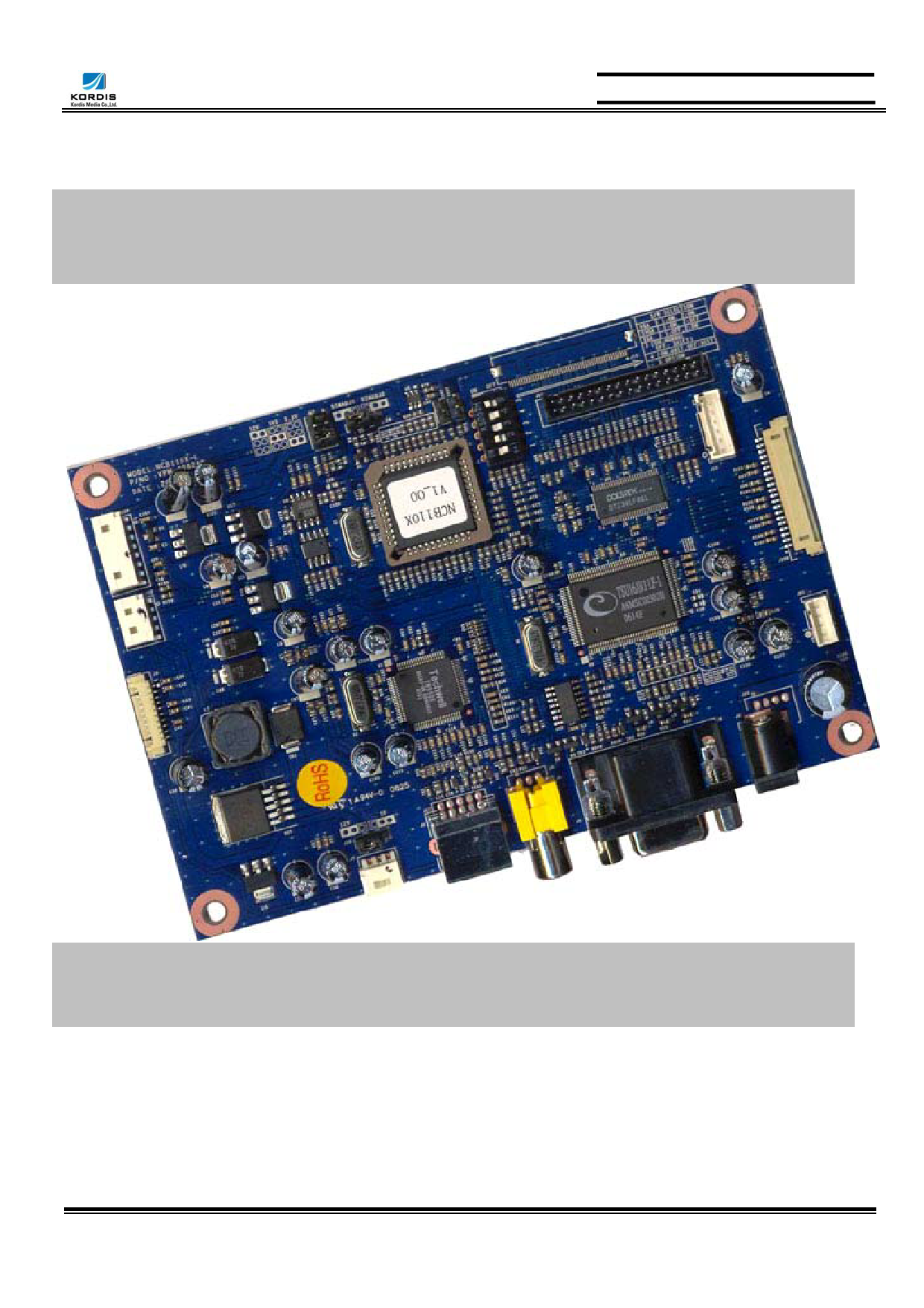
| Descripción | TFT LCD Monitor Control Board | |
| Fabricantes | Kordis Media | |
| Logotipo | ||
Hay una vista previa y un enlace de descarga de NCB110X3 (archivo pdf) en la parte inferior de esta página. Total 30 Páginas | ||
|
No Preview Available !
Data Sheet NCB110X3
For LCD Monitor (PC + Video) Interface Controller
For 640X480, 800X600 & 1024X768 Resolutions TFT LCD
DATA SHEET
TFT LCD Monitor Control Board
NCB110X3-DS-AB( RoHS Compliant )
July 2006
Kordis Media Co., ltd.
3F, 1006-9, Sadang-Dong,
Dongjak-Ku, Seoul
156-090, Korea
TEL : 82-2-585-8347
FAX : 82-2-585-8391
1
Kordis Media Co.,ltd.
1 page 
GENERAL SPECIFICATION
Data Sheet NCB110X3
No. Item
Description
For VGA panel
NCB110V3
1 Controller name For SVGA panel
NCB110S3
For XGA Panel
NCB110X3
2 LCD Module
VGA~XGA TFT LCD (TTL/LVDS Interface)
3 Signal Input
Resolution
4
Support
Analog RGB Input. NTSC/PAL
H: 31 ∼ 61kHz
V: 55 ∼ 76Hz
OSD Control
Menu, Select (AUTO), Down, Up(Source change), Power
5 keys
5
Plug & Play
VESA DDC 1/2B Ver1.3
6 Power Connector
Input Type: IEC320 MALE 3Line Connector
Supply Voltage
7. Power Consumption
12Vdc
cf) Back
Light Inverter
Max Power 30W (including Back Light Inverter)
Analog
15Pin D-SUB Connector
8 Signal Connector
Video
MINIDIN
RCA
SVHS
CVBS
5
Kordis Media Co.,ltd.
5 Page 
CONNECTION & OPERATION
Data Sheet NCB110X3
CAUTION: Never connect or disconnect parts of the display system when the system is powered up as this
may cause serious damage.
CONNECTION
1. LCD panel & inverter: Connect the inverter (if it is not built- in the panel) to the CCFT lead
connector of the LCD panel.
2. TTL type panels: Plug the signal cables direct to J14 (for Single 6bits, or Single (Dual first) higher
6bit, J13 (8bit dual (J13) and 8bits single lower 2bit) on the controller board. Plug the other end of
cables to the LCD connector board (if connector board is required, otherwise the signal can be
directly plugged to the LCD panel connector).
LVDS type panels: Plug the signal cables direct to J100 of the controller board. Plug the other end
of cables to the LCD connector board (if connector board is required, otherwise the signal can be
directly plugged to the LCD panel connector).
3. Inverter & Controller: Plug the inverter cable to J8 of the controller board and another end to the
connector on the inverter.
4. Function switch & Controller: Plug the OSD switch mount cable to J2 of the controller board and
another end to the OSD board.
5. Jumpers & Switch: Check all jumpers {J19 (External power Setting), J17 (Target panel power is
setting)} and switches (J14, Target panel selection) are set correctly. Details referring the jumpers
and switches setting table (in the following section)
6. VGA cable & Controller: Plug the VGA cable to the connector J3 of the controller board.
7. Power supply & Controller: Plug the DC 12V power in to the connector J7.
8. Power on: Switch on the controller board and panel by using the OSD switch mount.
General:
If you use supplied cables & accessories, ensure that they are correct for the model of the panel
and the controller.
If you make your own cables & connectors, refer carefully to both the panel & inverter
specifications and the section in this manual, “Connectors, Pin outs & Jumpers” to ensure the
correct pin to pin wiring.
PC Setting:
The controller has been designed to take a very wide range of input signals however to optimize the
PC’s graphic performance we recommend choosing 60Hz vertical refresh rate – this will not cause
screen flicker.
11
Kordis Media Co.,ltd.
11 Page | ||
| Páginas | Total 30 Páginas | |
| PDF Descargar | [ Datasheet NCB110X3.PDF ] | |
Hoja de datos destacado
| Número de pieza | Descripción | Fabricantes |
| NCB110X1 | TFT LCD Monitor Control Board | INNODISPLAY |
| NCB110X3 | TFT LCD Monitor Control Board | Kordis Media |
| Número de pieza | Descripción | Fabricantes |
| SLA6805M | High Voltage 3 phase Motor Driver IC. |
Sanken |
| SDC1742 | 12- and 14-Bit Hybrid Synchro / Resolver-to-Digital Converters. |
Analog Devices |
|
DataSheet.es es una pagina web que funciona como un repositorio de manuales o hoja de datos de muchos de los productos más populares, |
| DataSheet.es | 2020 | Privacy Policy | Contacto | Buscar |