|
|
|
PDF GT8G136 Data sheet ( Hoja de datos )
| Número de pieza | GT8G136 | |
| Descripción | Insulated Gate Bipolar Transistor | |
| Fabricantes | Toshiba Semiconductor | |
| Logotipo | ||
Hay una vista previa y un enlace de descarga de GT8G136 (archivo pdf) en la parte inferior de esta página. Total 6 Páginas | ||
|
No Preview Available !
TOSHIBA Insulated Gate Bipolar Transistor Silicon N Channel IGBT
GT8G136
Strobe Flash Applications
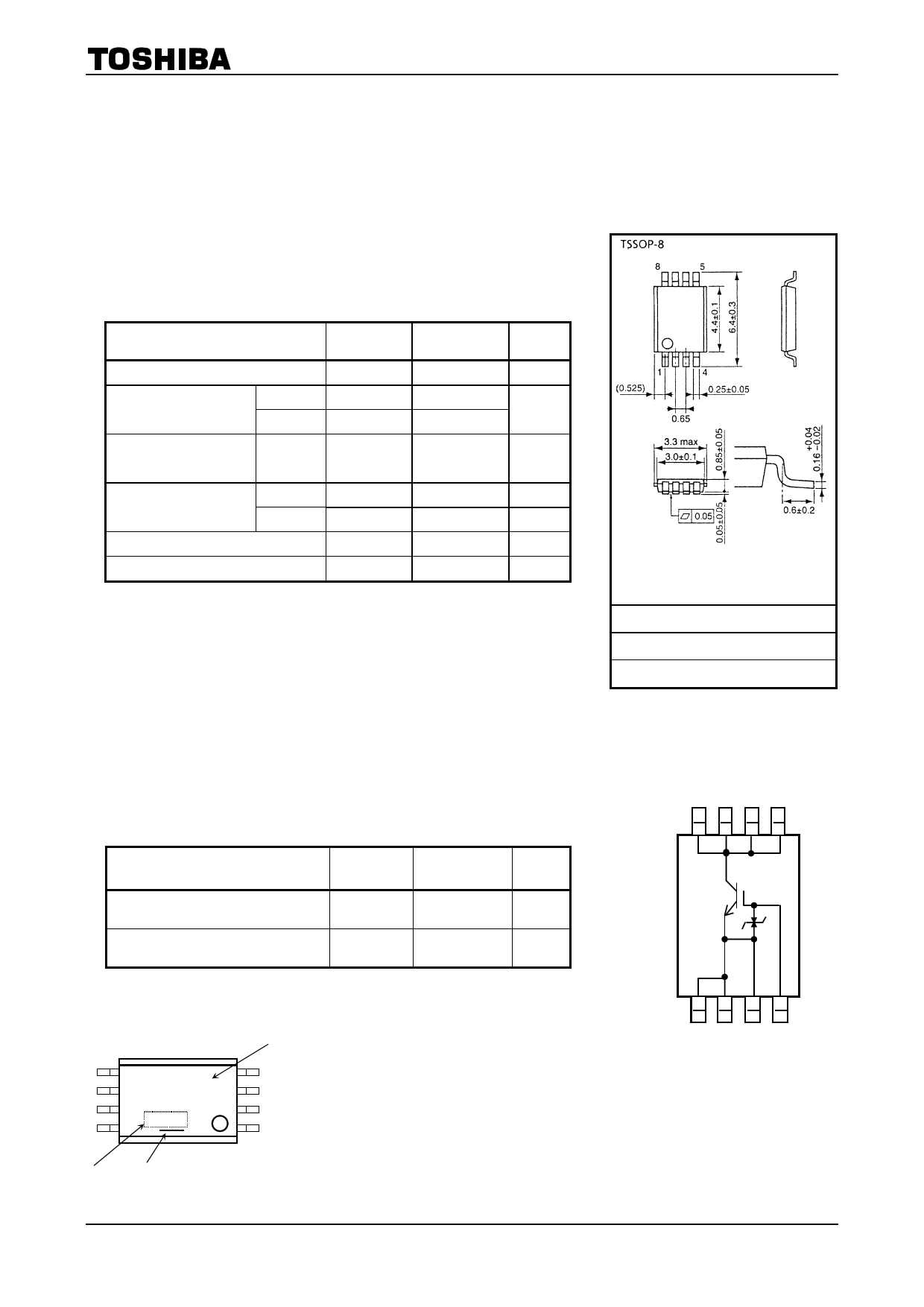
• Compact and Thin (TSSOP-8) package
• Enhancement-mode
• Peak collector current: IC = 150 A (max)
(@VGE=3.0V(min),Ta=70℃(max))/
Absolute Maximum Ratings (Ta = 25°C)
GT8G136
Unit: mm
Characteristics
Symbol
Rating
Unit
Collector-emitter voltage
Gate-emitter voltage
DC
Pulse
Collector current
Pulse
(Note 1)
Collector power
dissipation(t=10 s)
(Note 2a)
(Note 2b)
Junction temperature
Storage temperature range
VCES
VGES
VGES
ICP
PC (1)
PC (2)
Tj
Tstg
400
±6
±8
150
1.1
0.6
150
−55~150
V
V
A
W
W
°C
°C
Note: Using continuously under heavy loads (e.g. the application of high
temperature/current/voltage and the significant change in
temperature, etc.) may cause this product to decrease in the
reliability significantly even if the operating conditions (i.e.
operating temperature/current/voltage, etc.) are within the
absolute maximum ratings.
Please design the appropriate reliability upon reviewing the
Toshiba Semiconductor Reliability Handbook (“Handling
Precautions”/Derating Concept and Methods) and individual
reliability data (i.e. reliability test report and estimated failure rate,
etc).
Thermal Characteristics
1,2 EMITTER
3 EMITTER (Gate drive connection)
4 GATE
5,6,7,8 COLLECTOR
JEDEC
―
JEITA
―
TOSHIBA
-
Weight: 0.035 g (typ.)
Circuit Configuration
8765
Characteristics
Symbol
Rating
Unit
Thermal resistance , junction to
ambient (t = 10 s)
(Note2a)
Rth (j-a) (1)
114
°C/W
Thermal resistance , junction to
ambient (t = 10 s)
(Note2b)
Rth (j-a) (2)
208
°C/W
Marking (Note 3)
Note : For (Note 1) , (Note 2a) , (Note 2b) and (Note 3) , Please refer to the
next page.
Part No. (or abbreviation code)
5
6 8G136
7
8
4
3
2
1
1234
Lot No.
A line indicates
lead (Pb)-free package or
lead (Pb)-free finish.
1
2007-04-23
1 page 
Switching Time – RG
10
Common emitter
VCE = 300 V
VGE = 3 V
IC = 150 A
Ta
ton
3
toff
tf
tr
1
1 10 100 1000
Gate resistance RG (Ω)
Minimum Gate Drive Area
200
160
Ta
120
Ta 70
80
40
0
0246
Gate-emitter voltage VGE (V)
8
GT8G136
Switching Time – IC
10
tf
1
toff
ton
tr
0.1
0 50
Common emitter
VCC = 300 V
VGE = 3 V
RG = 51 Ω
Ta = 25°C
100 150
Collector current IC (A)
200
Maximum Operating Area
800
600
400
VCM = 350 V
200 Ta <= 70°C
VGE = 3.0 V
33 Ω <= RG <= 300 Ω
0
0 40 80 120 160
Peak collector current ICP (A)
200
5 2007-04-23
5 Page | ||
| Páginas | Total 6 Páginas | |
| PDF Descargar | [ Datasheet GT8G136.PDF ] | |
Hoja de datos destacado
| Número de pieza | Descripción | Fabricantes |
| GT8G131 | N CHANNEL MOS TYPE (STROBE FLASH APPLICATIONS) | Toshiba Semiconductor |
| GT8G132 | TOSHIBA Insulated Gate Bipolar Transistor Silicon N Channel IGBT | Toshiba Semiconductor |
| GT8G133 | Insulated Gate Bipolar Transistor | Toshiba Semiconductor |
| GT8G134 | Insulated Gate Bipolar Transistor | Toshiba Semiconductor |
| Número de pieza | Descripción | Fabricantes |
| SLA6805M | High Voltage 3 phase Motor Driver IC. |
Sanken |
| SDC1742 | 12- and 14-Bit Hybrid Synchro / Resolver-to-Digital Converters. |
Analog Devices |
|
DataSheet.es es una pagina web que funciona como un repositorio de manuales o hoja de datos de muchos de los productos más populares, |
| DataSheet.es | 2020 | Privacy Policy | Contacto | Buscar |