|
|
|
PDF IRFH4213DPbF Data sheet ( Hoja de datos )
| Número de pieza | IRFH4213DPbF | |
| Descripción | Power MOSFET ( Transistor ) | |
| Fabricantes | International Rectifier | |
| Logotipo | ||
Hay una vista previa y un enlace de descarga de IRFH4213DPbF (archivo pdf) en la parte inferior de esta página. Total 8 Páginas | ||
|
No Preview Available !
VDSS
RDS(on) max
(@ VGS = 10V)
(@ VGS = 4.5V)
Qg (typical)
ID
(@TC (Bottom) = 25°C)
25
1.35
1.90
25
100
V
m
nC
A
Applications
Synchronous Rectifier MOSFET for Synchronous Buck Converters
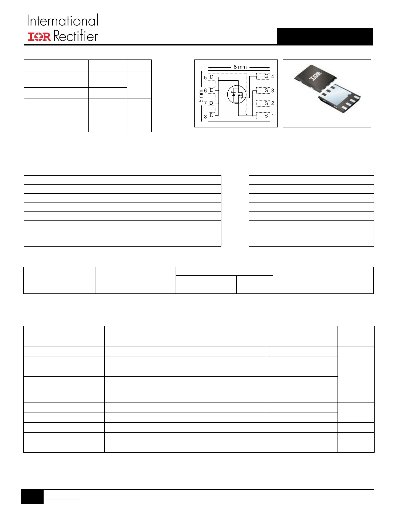
IRFH4213DPbF
HEXFET® Power MOSFET
PQFN 5X6 mm
Features
Low RDSon (<1.35m)
Schottky Intrinsic Diode with Low Forward Voltage
Low Thermal Resistance to PCB (<1.3°C/W)
Low Profile (<0.9 mm)
Industry-Standard Pinout
Compatible with Existing Surface Mount Techniques
RoHS Compliant, Halogen-Free
MSL1, Industrial Qualification
Benefits
Lower Conduction Losses
Lower Switching Losses
Enable better thermal dissipation
results in Increased Power Density
Multi-Vendor Compatibility
Easier Manufacturing
Environmentally Friendlier
Increased Reliability
Base part number
IRFH4213DPbF
Package Type
PQFN 5mm x 6 mm
Standard Pack
Form
Quantity
Tape and Reel
4000
Orderable Part Number
IRFH4213DTRPbF
Absolute Maximum Ratings
VGS
ID @ TA = 25°C
ID @ TC(Bottom) = 25°C
ID @ TC(Bottom) = 100°C
ID @ TC(Bottom) = 25°C
IDM
PD @TA = 25°C
PD @TC(Bottom) = 25°C
TJ
TSTG
Parameter
Gate-to-Source Voltage
Continuous Drain Current, VGS @ 10V
Continuous Drain Current, VGS @ 10V
Continuous Drain Current, VGS @ 10V
Continuous Drain Current, VGS @ 10V
(Source Bonding Technology Limited)
Pulsed Drain Current
Power Dissipation
Power Dissipation
Linear Derating Factor
Operating Junction and
Storage Temperature Range
Notes through are on page 8
1 www.irf.com © 2013 International Rectifier
Max.
± 20
40
208
131
100
400
3.6
96
0.029
-55 to + 150
Units
V
A
W
W/°C
°C
May 20, 2013
1 page 
6
ID = 50A
5
4
3
TJ = 125°C
2
1
TJ = 25°C
0
0 4 8 12 16 20
VGS, Gate-to-Source Voltage (V)
Fig 12. On– Resistance vs. Gate Voltage
1000
100
IRFH4213DPbF
800
ID
T OP
13A
26A
600 BOTT OM 50A
400
200
0
25
50 75 100 125
Starting T J, Junction Temperature (°C)
150
Fig 13. Maximum Avalanche Energy vs. Drain Current
Allowed avalanche Current vs avalanche
pulsewidth, tav, assuming Tj = 125°C and
Tstart =25°C (Single Pulse)
10
1 Allowed avalanche Current vs avalanche
pulsewidth, tav, assuming j = 25°C and
Tstart = 125°C.
0.1
1.0E-06
1.0E-05
1.0E-04
tav (sec)
1.0E-03
1.0E-02
Fig 14. Typical Avalanche Current vs. Pulsewidth
1.0E-01
5 www.irf.com © 2013 International Rectifier
May 20, 2013
5 Page | ||
| Páginas | Total 8 Páginas | |
| PDF Descargar | [ Datasheet IRFH4213DPbF.PDF ] | |
Hoja de datos destacado
| Número de pieza | Descripción | Fabricantes |
| IRFH4213DPbF | Power MOSFET ( Transistor ) | International Rectifier |
| Número de pieza | Descripción | Fabricantes |
| SLA6805M | High Voltage 3 phase Motor Driver IC. |
Sanken |
| SDC1742 | 12- and 14-Bit Hybrid Synchro / Resolver-to-Digital Converters. |
Analog Devices |
|
DataSheet.es es una pagina web que funciona como un repositorio de manuales o hoja de datos de muchos de los productos más populares, |
| DataSheet.es | 2020 | Privacy Policy | Contacto | Buscar |