|
|
|
PDF EMH7020-00ME08NRR Data sheet ( Hoja de datos )
| Número de pieza | EMH7020-00ME08NRR | |
| Descripción | 500KHz PWM Synchronous Boost Converter | |
| Fabricantes | Elite Semiconductor | |
| Logotipo | ||
Hay una vista previa y un enlace de descarga de EMH7020-00ME08NRR (archivo pdf) en la parte inferior de esta página. Total 15 Páginas | ||
|
No Preview Available !
ESMT/EMP
EMH7020
500mA, 500KHz PWM Synchronous Boost Converter
with Output Isolated During Shutdown
General Description
The EMH7020 is a high efficiency, synchronous fixed
frequency, current-mode step-up DC/DC converter.
During shutdown mode, the output is completely
isolated from the input without drawing any battery
current. The fixed 500KHz switching frequency obtains
maximum efficiency up to 96% and uses only a few
external components.
With 180Ω loading, the minimum start-up voltage can
be as low as 0.93V, provided by a one or two-cell
alkaline or one-cell Li-Lon battery.
The features of EMH7020 include current limit, low
battery comparator, open-drain power good output,
short circuit, and thermal shutdown protection. The
EMH7020 is also available in 3X3mm TDFN-10 and
E-MSOP-8L package.
Applications
Mobile Phone
Digital Still Cameras
Portable applications
MP3 Players
GPS Receivers
Features
Up to 96% efficiency
Reference voltage: 0.5V
Output to input disconnect at shutdown mode
500mA current delivery
Switch current limit protection
500KHz fixed switching frequency
Thermal shutdown protection
0.5V Low-battery comparator
Min-start up voltage: 0.93V
Low quiescent current: 50uA (Tpy.)
Low shutdown current < 1uA
TDFN 3x3mm 10 pins and E-MSOP 8 pins
package
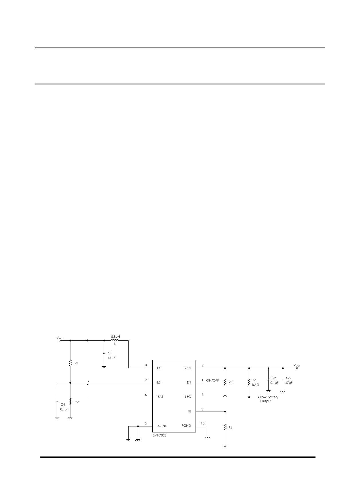
Typical Application
Elite Semiconductor Memory Technology Inc./Elite MicroPower Inc.
Publication Date: Jun. 2012
Revision: 1.2
1/15
1 page 
ESMT/EMP
EMH7020
Note 1: Absolute maximum ratings indicate limits beyond which damage may occur.
Note 2: All voltages are in respect to the potential of the ground pin.
Note 3: θJA is measured in the natural convection at TA=25℃ on a highly effective thermal conductivity test board (2
layers, 2S0P).
Note 4: θJC represents the thermal resistance between the chip and the top of the package case.
Note 5: Maximum power dissipation for the device is calculated using the following equation:
PD
TJ(MAX)
θJA
-
TA
Where TJ(MAX) is the maximum junction temperature, TA is the ambient temperature, and θ JA is the
junction-to-ambient thermal resistance. For example, for the TDFN-10 packageθJA = 110°C/W, TJ (MAX) =
150°C and using TA = 25°C, the maximum power dissipation is 1.136W. The derating factor (-1/θJA) =
-9.09mW/°C. Below 25°C the power dissipation figure can be increased by 9.09mW per degree and similarly
decreased by this factor for temperatures above 25°C.
Note 6: Typical values represent the most typical parametric norm.
Elite Semiconductor Memory Technology Inc./Elite MicroPower Inc.
Publication Date: Jun. 2012
Revision: 1.2
5/15
5 Page 
ESMT/EMP
EMH7020
Inductor Selection
The Inductor is required to force the output voltage higher while being driven by a lower input voltage. For most
applications, a 6.8uH inductor is used. An inductor with higher peak inductor current tends to provide a higher
output voltage ripple (IPEAK * output filter capacitor ESR). The inductor’s DC resistance can significantly affect
efficiency. The maximum output current can be calculated as follows:
IOUT(max)
VBAT
VOUT
[ICL
Toff(VOUT VBAT )]η
2L
(2)
IOUT(max) Maximum loading
VBAT Input voltage
L Inductor value in μH
η efficiency (~ 0.9 typically)
Toff LX switch's off - time in μs
ICL 1.5A
VENDOR
Sumida
EPCOS
WURTH ELEKTRONIK
SERIES
CDRH5D28R
B82462-G4
7447789
Table 2
VALUE
6.8μH
6.8μH
6.8μH
ISAT
1.5A
1.65A
2.75A
DCR
37mΩ
51mΩ
44mΩ
Input Capacitor Selection
A low ESR 10μF input capacitor is recommended to improve transient behavior and reduce the peak current
drawn from the battery. Ceramic capacitors are also a good choice for input decoupling and should be
located as close as possible to the device.
Output Capacitor Selection
The output ripple voltage relates with the peak inductor current and the output capacitor’s ESR. Multilayer
ceramic capacitors are an excellent choice as they have extremely low ESR. A 47μF output capacitor is
sufficient for most applications.
Elite Semiconductor Memory Technology Inc./Elite MicroPower Inc.
Publication Date: Jun. 2012
Revision: 1.2
11/15
11 Page | ||
| Páginas | Total 15 Páginas | |
| PDF Descargar | [ Datasheet EMH7020-00ME08NRR.PDF ] | |
Hoja de datos destacado
| Número de pieza | Descripción | Fabricantes |
| EMH7020-00ME08NRR | 500KHz PWM Synchronous Boost Converter | Elite Semiconductor |
| Número de pieza | Descripción | Fabricantes |
| SLA6805M | High Voltage 3 phase Motor Driver IC. |
Sanken |
| SDC1742 | 12- and 14-Bit Hybrid Synchro / Resolver-to-Digital Converters. |
Analog Devices |
|
DataSheet.es es una pagina web que funciona como un repositorio de manuales o hoja de datos de muchos de los productos más populares, |
| DataSheet.es | 2020 | Privacy Policy | Contacto | Buscar |