|
|
|
PDF MA5604 Data sheet ( Hoja de datos )
| Número de pieza | MA5604 | |
| Descripción | 38V 5A Synchronous Buck Converter | |
| Fabricantes | Major Power Technology | |
| Logotipo | ||
Hay una vista previa y un enlace de descarga de MA5604 (archivo pdf) en la parte inferior de esta página. Total 7 Páginas | ||
|
No Preview Available !
MA5604
38V 5A Synchronous Buck Converter
GENERAL DESCRIPTION
The MA5604 is a monolithic synchronous buck regulator. The device integrates internal high
side and external low side power MOSFETs, and provides 5A of continuous load current over a
wide input voltage of 8V to 38V. Current mode control provides fast transient response and
cycle-by-cycle current limit.
An internal soft-start prevents inrush current at turn-on, This device, available in SOP8L-EP
(Exposed pad) package, provides a very compact solution with minimal external components.
FEATURES
- Wide 8V to 38V Operating Input Range
- Integrated 90mΩ high side Power MOSFET Switches
- Output Adjustable from VFB(1V) to 20V
- Up to 95% Efficiency
- Internal Soft-Start
- Stable with Low ESR Ceramic Output Capacitors
- Fixed 160KHz Frequency
- Cycle-by-Cycle Over Current Protection
- Input Under/Over Voltage Lockout
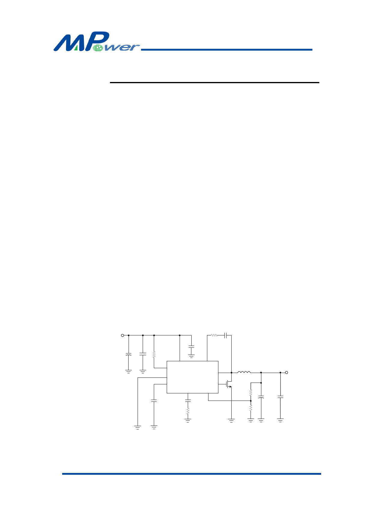
APPLICATION CIRCUIT
INPUT
C1
220μF
50V
C7
10μF
50V
R4
100kΩ
R5 C5
C6 0Ω 100nF
0.1μF
IN BS
EN MA5604 SW
PAD(GND)
VDD LG
COMP
FB
C4
0.1μF
3.3nF
C3
15kΩ R3
L1
33μH
Q1
NMOS
R1
40kΩ
R2
10kΩ
OUTPUT
5V 5A
C2
470μF
10V
C8
22μF
10V
VOUT=VFB × (1+R1/R2), VFB = 1.00V, R2 suggest 10k~30kΩ
Major Power Technology Co., Ltd.
1/7
Rev.1.0 Jun.04, 2014
1 page 
MA5604
FUNCTION DESCRIPTIONS
The MA5604 is a synchronous rectified, current-mode, step-down regulator. It regulates
input voltages from 8V to 38V down to an output voltage as low as VFB, and supplies up to 5A
of load current.
The MA5604 uses current-mode control to regulate the output voltage. The output voltage
is measured at FB through a resistive voltage divider and amplified through the internal Tran
conductance error amplifier. The voltage at the COMP pin is compared to the switch current
measured internally to control the output voltage.
The converter uses internal N-Channel MOSFET switches to step-down the input voltage
to the regulated output voltage. Since the high side MOSFET requires a gate voltage greater
than the input voltage, a boost capacitor connected between SW and BS is needed to drive the
high side gate. The boost capacitor is charged from the internal 5V rail when SW is low.
When the MA5604 FB pin exceeds 10% of the nominal regulation voltage of VFB, the over
voltage comparator is tripped and the COMP pin is discharged to GND, forcing the high-side
switch off.
APPLICATION INFORMATION
COMPONENT SELECTION
Setting the Output Voltage
The output voltage is set using a resistive voltage divider from the output voltage to FB
pin. The voltage divider divides the output voltage down to the feedback voltage by the ratio.
Thus the output voltage is:
VOUT=
VFB
×
R1 R2
R2
For example, VFB =1.00V for a 5.0V output voltage, R2 is 10kΩ, and R1 is 40kΩ.
Inductor Selection
The inductor is required to supply constant current to the output load while being driven
by the switched input voltage. A larger value inductor will result in less ripple current that will
result in lower output ripple voltage. However, the larger value inductor will have a larger
physical size, higher series resistance, and/or lower saturation current. A good rule for
determining the inductance to use is to allow the peak-to-peak ripple current in the inductor to
be approximately 30% of the maximum switch current limit.
VIN <28V <35V
Inductor
47uH
33uH
The choice of which style inductor to use mainly depends on the price vs. size
requirements and any EMI requirements.
Major Power Technology Co., Ltd.
5/7
Rev.1.0 Jun.04, 2014
5 Page | ||
| Páginas | Total 7 Páginas | |
| PDF Descargar | [ Datasheet MA5604.PDF ] | |
Hoja de datos destacado
| Número de pieza | Descripción | Fabricantes |
| MA5602 | 38V Synchronous Buck Converter | Major Power Technology |
| MA5604 | 38V 5A Synchronous Buck Converter | Major Power Technology |
| Número de pieza | Descripción | Fabricantes |
| SLA6805M | High Voltage 3 phase Motor Driver IC. |
Sanken |
| SDC1742 | 12- and 14-Bit Hybrid Synchro / Resolver-to-Digital Converters. |
Analog Devices |
|
DataSheet.es es una pagina web que funciona como un repositorio de manuales o hoja de datos de muchos de los productos más populares, |
| DataSheet.es | 2020 | Privacy Policy | Contacto | Buscar |