|
|
|
PDF NCV6354BMTAATBG Data sheet ( Hoja de datos )
| Número de pieza | NCV6354BMTAATBG | |
| Descripción | 3MHz 2A Fixed-Frequency Synchronous Buck Converter | |
| Fabricantes | ON Semiconductor | |
| Logotipo | ||
Hay una vista previa y un enlace de descarga de NCV6354BMTAATBG (archivo pdf) en la parte inferior de esta página. Total 15 Páginas | ||
|
No Preview Available !
NCV6354
3MHz, 2A Fixed-Frequency
Synchronous Buck
Converter
High Efficiency, Low Ripple, Adjustable
Output Voltage
The NCV6354, a synchronous buck converter, which is optimized
to supply the different sub systems of portable applications powered
by one cell Li−ion or three cell Alkaline/NiCd/NiMH batteries. The
device is able to deliver up to 2 A on an external adjustable voltage.
Operation with 3 MHz switching frequency allows employing small
size inductor and capacitors. Input supply voltage feedforward control
is employed to deal with wide input voltage range. Synchronous
rectification offers improved system efficiency. The NCV6354 is in a
space saving, low profile 2.0x2.0x0.75 mm WDFN−8 package.
Features
• 2.3 V to 5.5 V Input Voltage Range
• External Adjustable Voltage
• Up to 2 A Output Current
• 3 MHz Switching Frequency
• Synchronous Rectification
• Enable Input
• Power Good Output
• Soft Start
• Over Current Protection
• Active Discharge when Disabled
• Thermal Shutdown Protection
• WDFN−8, 2x2 mm, 0.5 mm Pitch Package
• Maximum 0.8 mm Height for Super Thin Applications
• These are Pb−Free Devices
Typical Applications
• Cellular Phones, Smart Phones, and PDAs
• Portable Media Players
• Digital Still Cameras
• Wireless and DSL Modems
• USB Powered Devices
• Point of Load
• Game and Entertainment System
http://onsemi.com
1
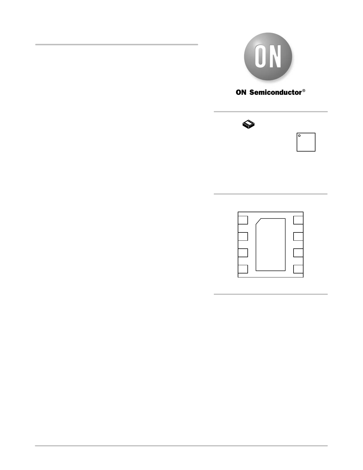
WDFN8
CASE 511BT
MARKING
DIAGRAM
1
ADMG
G
AD = Specific Device Code
M = Date Code
G = Pb−Free Package
(*Note: Microdot may be in either location)
BLOCK DIAGRAM
PGND 1
SW 2
AGND 3
FB 4
9
(Top View)
8 PVIN
7 AVIN
6 PG
5 EN
ORDERING INFORMATION
See detailed ordering, marking and shipping information in the
package dimensions section on page 14 of this data sheet.
© Semiconductor Components Industries, LLC, 2012
November, 2012 − Rev. 4
1
Publication Order Number:
NCV6354/D
1 page 
NCV6354
ELECTRICAL CHARACTERISTICS
(VIN = 3.6 V, VOUT = 1.8 V, L = 1 mH, C = 10 mF, typical values are referenced to TJ = 25°C, Min and Max values are referenced to TJ up to
125°C. unless other noted.)
Characteristics
Test Conditions
Symbol Min Typ Max Unit
SOFT START
Soft−Start Time
Time from EN to 90% of output voltage
target
TSS
− 0.4 1 ms
CONTROL LOGIC
EN Input High Voltage
VEN_H
1.1
−
−
V
EN Input Low Voltage
VEN_L
−
− 0.4 V
EN Input Hysteresis
VEN_HYS
−
270
−
mV
Enable Input Bias Current
OUTPUT ACTIVE DISCHARGE
IEN_BIAS
0.1 1 mA
Internal Output Discharge Resistance
THERMAL SHUTDOWN
from SW to PGND
R_DIS 75 500 700 W
Thermal Shutdown Threshold
TSD
− 160 −
Thermal Shutdown Hysteresis
TSD_HYS
−
25
−
7. Guaranteed by design, not tested in production.
8. Maximum value applies for TJ = 85°C.
9. Operation above 5.5 V input voltage for extended periods may affect device reliability.
°C
°C
http://onsemi.com
5
5 Page 
NCV6354
VOUT_PP(C)
+
8
IL_PP
@ C @ fSW
VOUT_PP(ESR) + IL_PP @ ESR
(eq. 6)
(eq. 7)
VOUT_PP(ESL)
+
ESL
ESL )
L
@
VIN
and the peak−to−peak ripple current is
(eq. 8)
IL_PP
+
ǒVIN * VOUTǓ
VIN @ fSW
@
@
VOUT
L
(eq. 9)
In applications with all ceramic output capacitors, the
main ripple component of the output ripple is VOUT_PP(C).
So that the minimum output capacitance can be calculated
regarding to a given output ripple requirement VOUT_PP in
PWM operation mode.
CMIN
+
8
@
IL_PP
VOUT_PP
@
fSW
(eq. 10)
Input Capacitor Selection
One of the input capacitor selection guides is the input
voltage ripple requirement. To minimize the input voltage
ripple and get better decoupling in the input power supply
rail, ceramic capacitor is recommended due to low ESR and
ESL. The minimum input capacitance regarding to the input
ripple voltage VIN_PP is
CIN_MIN
+
IOUT_MAX @ ǒD *
VIN_PP @ fSW
D2Ǔ
(eq. 11)
where
D
+
VOUT
VIN
(eq. 12)
In addition, the input capacitor needs to be able to absorb
the input current, which has a RMS value of
IIN_RMS + IOUT_MAX @ ǸD * D2
(eq. 13)
The input capacitor also needs to be sufficient to protect
the device from over voltage spike, and normally at least a
4.7 mF capacitor is required. The input capacitor should be
located as close as possible to the IC on PCB.
Table 3. LIST OF RECOMMENDED INPUT CAPACITORS AND OUTPUT CAPACITORS
Manufacturer
Part Number
Case
Height
Size Max (mm) C (mF)
Rated Voltage (V)
MURATA
GRM21BR60J226ME39, X5R
0805
1.4
22
6.3
TDK
C2012X5R0J226M, X5R
0805
1.25
22
6.3
MURATA
GRM21BR61A106KE19, X5R
0805
1.35
10
10
TDK
C2012X5R1A106M, X5R
0805
1.25
10
10
MURATA
GRM188R60J106ME47, X5R
0603
0.9
10
6.3
TDK
C1608X5R0J106M, X5R
0603
0.8
10
6.3
MURATA
GRM188R60J475KE19, X5R
0603
0.87
4.7
6.3
Structure
MLCC
MLCC
MLCC
MLCC
MLCC
MLCC
MLCC
Design of Feedback Network
For NCV6354 devices with an external adjustable output
voltage, the output voltage is programmed by an external
resistor divider connected from VOUT to FB and then to
AGND, as shown in the typical application schematic
Figure 1a. The programmed output voltage is
ǒ ǓVOUT + VFB @
1
)
R1
R2
(eq. 14)
where VFB is equal to the internal reference voltage 0.6 V,
R1 is the resistance from VOUT to FB, which has a normal
value range from 50 kW to 1 MW and a typical value of
220 kW for applications with the typical output filter. R2 is
the resistance from FB to AGND, which is used to program
the output voltage according to Equation 14 once the value
of R1 has been selected. An capacitor Cfb needs to be
employed between the VOUT and FB in order to provide
feedforward function to achieve optimum transient
response. Normal value range of Cfb is from 0 to 100pF, and
a typical value is 15 pF for applications with the typical
output filter and R1 = 220 kW.
Table 4 provides reference values of R1 and Cfb in case of
different output filter combinations. The final design may
need to be fine tuned regarding to application specifications.
http://onsemi.com
11
11 Page | ||
| Páginas | Total 15 Páginas | |
| PDF Descargar | [ Datasheet NCV6354BMTAATBG.PDF ] | |
Hoja de datos destacado
| Número de pieza | Descripción | Fabricantes |
| NCV6354BMTAATBG | 3MHz 2A Fixed-Frequency Synchronous Buck Converter | ON Semiconductor |
| Número de pieza | Descripción | Fabricantes |
| SLA6805M | High Voltage 3 phase Motor Driver IC. |
Sanken |
| SDC1742 | 12- and 14-Bit Hybrid Synchro / Resolver-to-Digital Converters. |
Analog Devices |
|
DataSheet.es es una pagina web que funciona como un repositorio de manuales o hoja de datos de muchos de los productos más populares, |
| DataSheet.es | 2020 | Privacy Policy | Contacto | Buscar |