|
|
|
PDF 3EZ39D5 Data sheet ( Hoja de datos )
| Número de pieza | 3EZ39D5 | |
| Descripción | Zener Voltage Regulators | |
| Fabricantes | ON Semiconductor | |
| Logotipo | ||
Hay una vista previa y un enlace de descarga de 3EZ39D5 (archivo pdf) en la parte inferior de esta página. Total 7 Páginas | ||
|
No Preview Available !
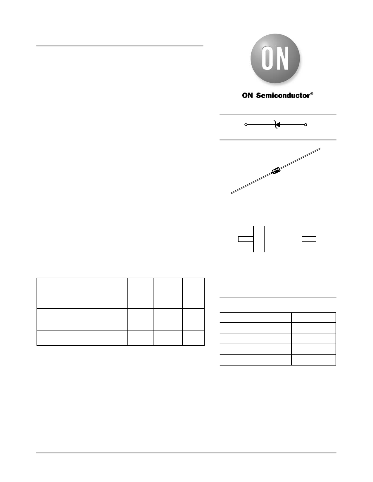
3EZ4.3D5 Series
3 Watt DO−41 SurmeticE 30
Zener Voltage Regulators
This is a complete series of 3 Watt Zener diodes with limits and
excellent operating characteristics that reflect the superior capabilities
of silicon−oxide passivated junctions. All this in an axial−lead,
transfer−molded plastic package that offers protection in all common
environmental conditions.
Specification Features:
• Zener Voltage Range − 4.3 V to 330 V
• ESD Rating of Class 3 (>16 KV) per Human Body Model
• Surge Rating of 98 W @ 1 ms
• Maximum Limits Guaranteed on up to Six Electrical Parameters
• Package No Larger than the Conventional 1 Watt Package
w These devices are available in Pb−free package(s). Specifications herein
apply to both standard and Pb−free devices. Please see our website at
www.onsemi.com for specific Pb−free orderable part numbers, or
contact your local ON Semiconductor sales office or representative.
Mechanical Characteristics:
CASE: Void free, transfer−molded, thermosetting plastic
FINISH: All external surfaces are corrosion resistant and leads are
readily solderable
MAXIMUM LEAD TEMPERATURE FOR SOLDERING PURPOSES:
230°C, 1/16″ from the case for 10 seconds
POLARITY: Cathode indicated by polarity band
MOUNTING POSITION: Any
MAXIMUM RATINGS
Rating
Max. Steady State Power Dissipation
@ TL = 75°C, Lead Length = 3/8″
Derate above 75°C
Steady State Power Dissipation
@ TA = 50°C
Derate above 50°C
Operating and Storage
Temperature Range
Symbol
PD
PD
TJ, Tstg
Value
3
24
1
6.67
−65 to
+200
Unit
W
mW/°C
W
mW/°C
°C
http://onsemi.com
Cathode
Anode
AXIAL LEAD
CASE 59
PLASTIC
MARKING DIAGRAM
L
3EZx
xxD5
YYWW
L = Assembly Location
3EZxxxD5 = Device Code
= (See Table Next Page)
YY = Year
WW = Work Week
ORDERING INFORMATION
Device
Package
Shipping
3EZxxxD5
Axial Lead 2000 Units/Box
3EZxxxD5RL*
Axial Lead 6000/Tape & Reel
3EZxxxD5RR1 { Axial Lead 2000/Tape & Reel
3EZxxxD5RR2 } Axial Lead 2000/Tape & Reel
†Polarity band up with cathode lead off first
} Polarity band down with cathode lead off first
*3EZ8.2D5 and 3EZ220D5 Not Available
6000/Tape & Reel
in
© Semiconductor Components Industries, LLC, 2006
March, 2006 − Rev. 4
1
Publication Order Number:
3EZ4.3D5/D
1 page 
3EZ4.3D5 Series
APPLICATION NOTE
Since the actual voltage available from a given zener
diode is temperature dependent, it is necessary to determine
junction temperature under any set of operating conditions
in order to calculate its value. The following procedure is
recommended:
Lead Temperature, TL, should be determined from:
TL = qLA PD + TA
qLA is the lead-to-ambient thermal resistance (°C/W) and
PD is the power dissipation. The value for qLA will vary and
depends on the device mounting method. qLA is generally
30−40°C/W for the various clips and tie points in common
use and for printed circuit board wiring.
The temperature of the lead can also be measured using a
thermocouple placed on the lead as close as possible to the
tie point. The thermal mass connected to the tie point is
normally large enough so that it will not significantly
respond to heat surges generated in the diode as a result of
pulsed operation once steady-state conditions are achieved.
Using the measured value of TL, the junction temperature
may be determined by:
TJ = TL + DTJL
DTJL is the increase in junction temperature above the lead
temperature and may be found from Figure 2 for a train of
power pulses (L = 3/8 inch) or from Figure 10 for dc power.
DTJL = qJL PD
For worst-case design, using expected limits of IZ, limits
of PD and the extremes of TJ (DTJ) may be estimated.
Changes in voltage, VZ, can then be found from:
DV = qVZ DTJ
qVZ, the zener voltage temperature coefficient, is found
from Figures 5 and 6.
Under high power-pulse operation, the zener voltage will
vary with time and may also be affected significantly by the
zener resistance. For best regulation, keep current
excursions as low as possible.
Data of Figure 2 should not be used to compute surge
capability. Surge limitations are given in Figure 3. They are
lower than would be expected by considering only junction
temperature, as current crowding effects cause temperatures
to be extremely high in small spots resulting in device
degradation should the limits of Figure 3 be exceeded.
http://onsemi.com
5
5 Page | ||
| Páginas | Total 7 Páginas | |
| PDF Descargar | [ Datasheet 3EZ39D5.PDF ] | |
Hoja de datos destacado
| Número de pieza | Descripción | Fabricantes |
| 3EZ39D10 | SILICON ZENER DIODES | EIC |
| 3EZ39D5 | SILICON 3 WATT ZENER DIODES | Microsemi Corporation |
| 3EZ39D5 | 3W SILICON ZENER DIODE | Jinan Gude Electronic Device |
| 3EZ39D5 | SILICON ZENER DIODES | EIC discrete Semiconductors |
| Número de pieza | Descripción | Fabricantes |
| SLA6805M | High Voltage 3 phase Motor Driver IC. |
Sanken |
| SDC1742 | 12- and 14-Bit Hybrid Synchro / Resolver-to-Digital Converters. |
Analog Devices |
|
DataSheet.es es una pagina web que funciona como un repositorio de manuales o hoja de datos de muchos de los productos más populares, |
| DataSheet.es | 2020 | Privacy Policy | Contacto | Buscar |