|
|
|
PDF HCPL2601M Data sheet ( Hoja de datos )
| Número de pieza | HCPL2601M | |
| Descripción | Single-Channel High-Speed 10 MBit/s Logic Gate Optocouplers | |
| Fabricantes | Fairchild Semiconductor | |
| Logotipo | ||
Hay una vista previa y un enlace de descarga de HCPL2601M (archivo pdf) en la parte inferior de esta página. Total 18 Páginas | ||
|
No Preview Available !
April 2013
Single-Channel: 6N137M, HCPL2601M, HCPL2611M
Dual-Channel: HCPL2630M, HCPL2631M
High-Speed 10 MBit/s Logic Gate Optocouplers
Features
■ Very High Speed – 10 MBit/s
■ Superior CMR – 10 kV/µs
■ Fan-out of 8 Over -40°C to +85°C
■ Logic Gate Output
■ Strobable Output
■ Wired OR-open Collector
■ U.L. Recognized (File # E90700, Vol. 2)
Applications
■ Ground Loop Elimination
■ LSTTL to TTL, LSTTL or 5 V CMOS
■ Line Receiver, Data Transmission
■ Data Multiplexing
■ Switching Power Supplies
■ Pulse Transformer Replacement
■ Computer-peripheral Interface
Description
The 6N137M, HCPL2601M, HCPL2611M single-channel
and HCPL2630M, HCPL2631M dual-channel optocou-
plers consist of a 850 nm AlGaAS LED, optically coupled
to a very high speed integrated photo-detector logic gate
with a strobable output. This output features an open col-
lector, thereby permitting wired OR outputs. The
switching parameters are guaranteed over the tempera-
ture range of -40°C to +85°C. A maximum input signal of
5 mA will provide a minimum output sink current of
13 mA (fan out of 8).
An internal noise shield provides superior common
mode rejection of typically 10 kV/µs. The HCPL2601M
and HCPL2631M has a minimum CMR of 5 kV/µs. The
HCPL2611M has a minimum CMR of 10 kV/µs.
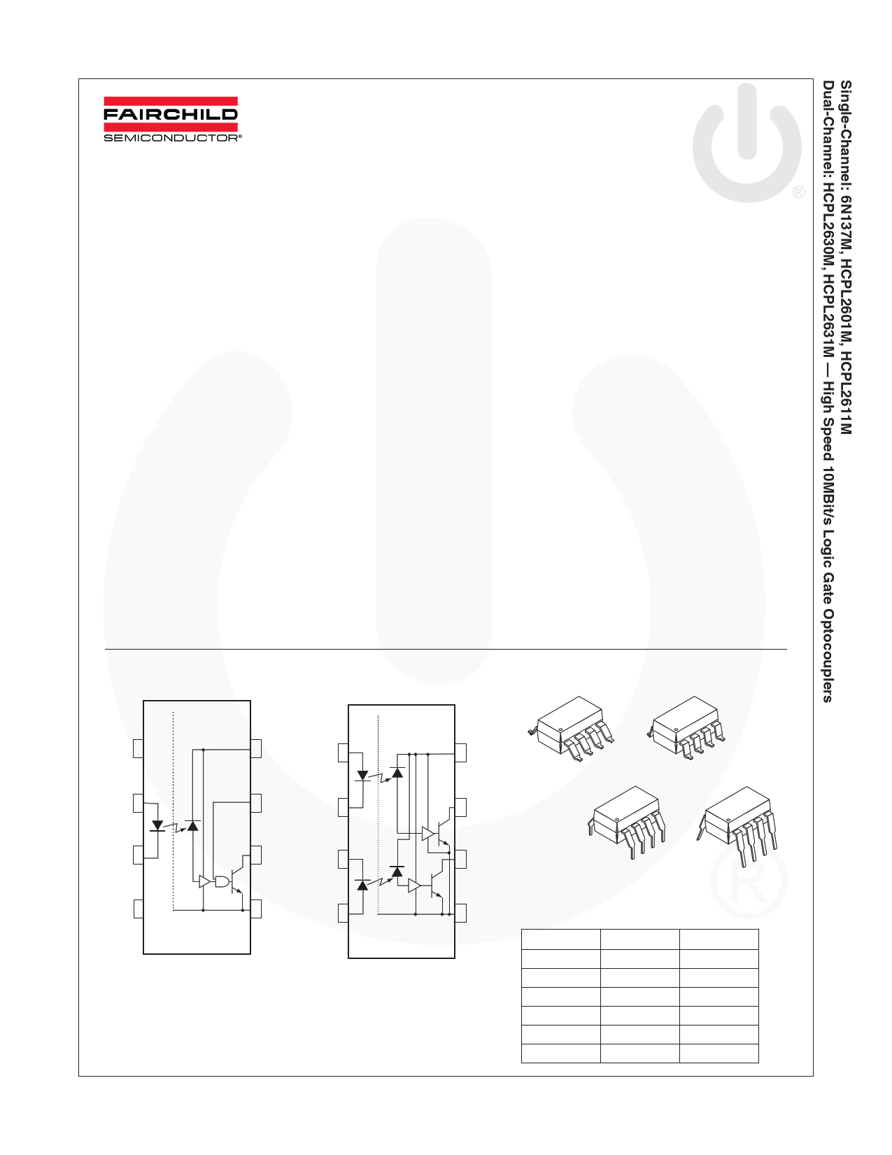
Schematics
Package Outlines
N/C 1
+2
V
F
_3
N/C 4
8
V
CC
7V
E
+1
V
F1
_2
6V
O
5 GND
_3
V
F2
+4
8
V
CC
7V
01
6V
02
5 GND
6N137M
HCPL2601M
HCPL2611M
HCPL2630M
HCPL2631M
(Preliminary)
A 0.1µF bypass capacitor must be connected between pins 8 and 5(1).
Figure 1. Schematics
©2009 Fairchild Semiconductor Corporation
6N137M, HCPL26XXM Rev. 1.0.8
8
1
8
1
8
8
1
1
Figure 2. Package Options
Truth Table (Positive Logic)
Input
Enable
HH
LH
HL
LL
H NC
L NC
Output
L
H
H
H
L
H
www.fairchildsemi.com
1 page 
Electrical Characteristics (Continued)
Transfer Characteristics (TA = -40 to +85°C unless otherwise specified)
Symbol DC Characteristics
Test Conditions
IOH HIGH Level Output Current VCC = 5.5 V, VO = 5.5 V,
IF = 250 µA, VE = 2.0 V(2)
VOL LOW Level Output Current VCC = 5.5 V, IF = 5 mA, VE = 2.0 V,
ICL = 13 mA(2)
IFT Input Threshold Current
VCC = 5.5 V, VO = 0.6 V, VE = 2.0 V,
IOL = 13 mA
Min.
Typ.* Max.
100
0.4 0.6
35
Unit
µA
V
mA
Isolation Characteristics (TA = -40°C to +85°C unless otherwise specified.)
Symbol
Characteristics
Test Conditions
Min.
II-O
VISO
RI-O
CI-O
Input-Output Insulation
Leakage Current
Withstand Insulation Test
Voltage
Resistance (Input to Output)
Capacitance (Input to Output)
Relative humidity = 45%,
TA = 25°C, t = 5 s,
VI-O = 3000 VDC(12)
RH < 50%, TA = 25°C,
II-O ≤ 10 µA, t = 1 min.(12)
VI-O = 500 V(12)
f = 1 MHz(12)
5000
*All Typicals at VCC = 5 V, TA = 25°C
Typ.*
1011
1
Max.
1.0*
Unit
µA
VRMS
Ω
pF
Notes:
1. The VCC supply to each optoisolator must be bypassed by a 0.1 µF capacitor or larger. This can be either a ceramic
or solid tantalum capacitor with good high frequency characteristic and should be connected as close as possible
to the package VCC and GND pins of each device.
2. Each channel.
3. Enable Input – No pull up resistor required as the device has an internal pull up resistor.
4. tPLH – Propagation delay is measured from the 3.75 mA level on the HIGH to LOW transition of the input current
pulse to the 1.5 V level on the LOW to HIGH transition of the output voltage pulse.
5. tPHL – Propagation delay is measured from the 3.75 mA level on the LOW to HIGH transition of the input current
pulse to the 1.5 V level on the HIGH to LOW transition of the output voltage pulse.
6. tr – Rise time is measured from the 90% to the 10% levels on the LOW to HIGH transition of the output pulse.
7. tf – Fall time is measured from the 10% to the 90% levels on the HIGH to LOW transition of the output pulse.
8. tELH – Enable input propagation delay is measured from the 1.5 V level on the HIGH to LOW transition of the input
voltage pulse to the 1.5 V level on the LOW to HIGH transition of the output voltage pulse.
9. tEHL – Enable input propagation delay is measured from the 1.5 V level on the LOW to HIGH transition of the input
voltage pulse to the 1.5 V level on the HIGH to LOW transition of the output voltage pulse.
10. CMH – The maximum tolerable rate of rise of the common mode voltage to ensure the output will remain in the
HIGH state (i.e., VOUT > 2.0 V). Measured in volts per microsecond (V/µs).
11. CML – The maximum tolerable rate of rise of the common mode voltage to ensure the output will remain in the
LOW output state (i.e., VOUT < 0.8 V). Measured in volts per microsecond (V/µs).
12. Device considered a two-terminal device: Pins 1, 2, 3 and 4 shorted together, and Pins 5, 6, 7 and 8 shorted
together.
©2009 Fairchild Semiconductor Corporation
6N137M, HCPL26XXM Rev. 1.0.8
5
www.fairchildsemi.com
5 Page 
Test Circuits (Continued)
A
B
VFF
IF
1
2
3
VCC
8
7 .1 μF
bypass
6
45
GND
VCM
Pulse Gen
+5 V
350 Ω
Output
(VO)
Peak
VCM
0V
5V
VO
VO
0.5 V
Switching Pos. (A), IF= 0
VO (Min)
VO (Max)
Switching Pos. (B), IF = 7.5 mA
CM H
CM L
Figure 26. Test Circuit Common Mode Transient Immunity
©2009 Fairchild Semiconductor Corporation
6N137M, HCPL26XXM Rev. 1.0.8
11
www.fairchildsemi.com
11 Page | ||
| Páginas | Total 18 Páginas | |
| PDF Descargar | [ Datasheet HCPL2601M.PDF ] | |
Hoja de datos destacado
| Número de pieza | Descripción | Fabricantes |
| HCPL2601 | High CMR/ High Speed TTL Compatible Optocouplers | Agilent(Hewlett-Packard) |
| HCPL2601 | Optocoupler/Optoisolator | Texas Instruments |
| HCPL2601 | High Speed 10MBit/s Logic Gate Optocouplers | Fairchild Semiconductor |
| HCPL2601M | Single-Channel High-Speed 10 MBit/s Logic Gate Optocouplers | Fairchild Semiconductor |
| Número de pieza | Descripción | Fabricantes |
| SLA6805M | High Voltage 3 phase Motor Driver IC. |
Sanken |
| SDC1742 | 12- and 14-Bit Hybrid Synchro / Resolver-to-Digital Converters. |
Analog Devices |
|
DataSheet.es es una pagina web que funciona como un repositorio de manuales o hoja de datos de muchos de los productos más populares, |
| DataSheet.es | 2020 | Privacy Policy | Contacto | Buscar |