|
|
|
PDF MAx-305 Data sheet ( Hoja de datos )
| Número de pieza | MAx-305 | |
| Descripción | Two-Position Actuators General Instructions | |
| Fabricantes | Schneider | |
| Logotipo | ||
Hay una vista previa y un enlace de descarga de MAx-305 (archivo pdf) en la parte inferior de esta página. Total 12 Páginas | ||
|
No Preview Available !
MAx-305 & MAx-318 Series
MAx-405 Through MAx-419
Series
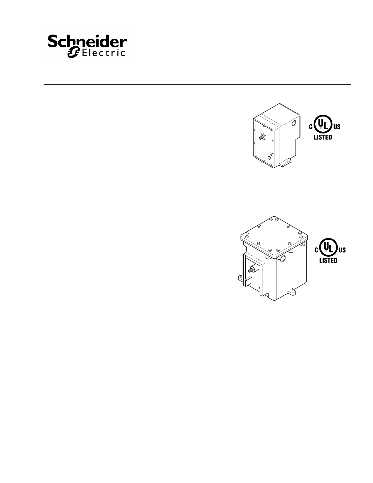
Two-Position Actuators
General Instructions
Application
For two-position operation of dampers, valves, and
other equipment which require the return to normal
position upon power interruption.
Hazardous location models offer a sturdy cast
aluminum case with bolted cover. They have two 3/4"
pipe tapped openings for joints with rigid metal conduit.
All wiring is brought out to separate terminals for ease
of installation. These factory enclosure and actuator
assemblies are Underwriters Laboratories listed.
Features
• Compatible with most SPST control devices
• Spring return
• 24, 120, 208, and 240 Vac models
• Actuators with part number suffix "-500" are
equipped with SPDT auxiliary switch
• Actuator has a rugged die cast aluminum housing
with two 1/2” conduit openings
• Hazardous location actuator housing has two 3/4"
pipe taped openings for rigid metal conduit
connection
• Oil immersed motor and gear train
MA-3xx, MA5-318,
MA-4xx, MA5-419
(Standard)
MA6-3xx, MA6-4xx, MA7-4xx,
MA8-3xx, MA8-4xx
(Hazardous Locations)
Applicable Literature
• Electric/Electronic Products Catalog, F-27382
• Valve Products Catalog, F-27384
• Cross-Reference Guide, F-26789
• AV-29x Valve Linkage for Hazardous Location Gear
Train Actuators General Instructions, F-27441.
• Apparatus for Hazardous Locations EN-56-2,
F-18451.
• AV-390 Series, Valve Linkage for Gear Train
Actuators General Instructions, F-24376.
• Material Safety Data Sheet (MSDS) for BCS-51-168
Oil (Until Feb. 1989)
• Material Safety Data Sheet (MSDS) for BCS-51-185
Oil (Until March 2002) (MAx-3xx-x-x-3 and
MAx-4xx-x-x-3)
• Material Safety Data Sheet (MSDS) for
BCS-51-185-1 Oil (Current) (MAx-3xx-x-x-4 and
MAx-4xx-x-x-4)
• High Temperature Exposure Performance (UL 555S)
MAx-31x-x-x-4, MAx-41x-x-x-4 Series Actuators
Engineering Information EN-216, F-27068
Printed in U.S.A. 6/12
© Copyright 2012 Schneider Electric All Rights Reserved.
F-06491-32
1 page 
INSTALLATION
Inspection
Requirements
Mounting
F-06491-32
Inspect the package for damage. If damaged, notify the appropriate carrier immediately.
If undamaged, open the package and inspect the device for obvious damage. Return damaged
products.
• Job wiring diagrams
• Tools (not provided):
– Digital Volt-ohm Meter (DVM)
– Appropriate screwdriver(s) for cover and mounting screws
– Appropriate drill and drill bit for mounting screws
– Appropriate wrenches for adjustment of damper and valve linkages
• Appropriate accessories
• Mounting screws (not provided)
• Training: Installer must be a qualified, experienced technician
Warning:
• Disconnect the power supply (line power) before installation to prevent electrical shock and
equipment damage.
• Make all connections in accordance with the wiring diagram and in accordance with
national and local electrical codes. Use copper conductors only.
Caution:
• Do not apply power to the unit unless the damper linkage and/or the valve assembly have
been installed.
• Avoid locations where excessive oil, dust, moisture, corrosive fumes or vibration, or an
explosive atmosphere is present. The actuator case is intended primarily to provide a
degree of protection against windblown dust, rain, sleet, and external ice formation (NEMA
Type 4).
Mount the actuator according to the following requirements:
1. Allow a minimum of 6" (152 mm) clearance behind the actuator for access to the wiring
compartment.
2. Locate the actuator in a weather-protected area.
3. To ensure water and weather resistance, install the cover gasket (provided) and use
water-tight conduit fittings.
Dampers
Install the actuator and the damper linkage, so that 180° of actuator shaft rotation drives 90° of
damper shaft rotation, as follows:
Actuator Mounting and Damper Linkage Installation
1. Mount the actuator in an appropriate position near the damper.
Note:
• MA-305 and MA-405 series actuators are not position-sensitive, and in damper applications,
may be mounted in any position. However, the upright position is preferred.
• MA-318, MA-416, MA-418, and MA-419 series actuators must be mounted so that the
output shaft lies in a horizontal position.
• To the extent possible, position the actuator to optimize the length of the damper rod
needed to link it with the damper. A damper rod that is too long is not rigid enough for good
control, and a damper rod that is too short makes it difficult to adjust the linkage.
2. Install crank arms onto the driven shaft and the actuator shaft. Tighten the crank arm on the
driven shaft. Do not tighten the crank arm on the actuator shaft at this time.
3. Install a linkage connector onto the actuator shaft crank arm, at the prick point. Refer to
(Figure-3) and (Figure-4).
© Copyright 2012 Schneider Electric All Rights Reserved.
5
5 Page 
MAINTENANCE
Caution: MA-300 series and MA-400 series actuators that are used in applications where they
are energized for extended periods of time must be electrically cycled at least once every six
months to ensure correct operation.
Regular maintenance of the total system is recommended to assure sustained, optimum
performance.
FIELD REPAIR
None. Replace an inoperative actuator with a functional unit.
DIMENSIONAL DATA
4-3/4 (121)
3-3/8
(86)
4-1/2
(114)
1/2 (13) Conduit
Opening on Each Side
15/16 (24)
1/2 (13)
Dia. Shaft
4 (102)
3-7/8
(98)
5-3/4
(146)
1/4 (6)
17/64 (7)
Dia. Hole
(1 of 3)
4-1/4 (108)
5-5/8 (143)
2-1/4
(57)
1-1/2
(38)
5-3/8 (136)
Dimensions are in inches (mm).
4-3/4
(121)
1-7/16 (37)
13/16 (21)
Figure-9 Dimensions of MA-3xx, MA5-318, MA-4xx, and MA5-419 (Standard) Actuators.
F-06491-32
© Copyright 2012 Schneider Electric All Rights Reserved.
11
11 Page | ||
| Páginas | Total 12 Páginas | |
| PDF Descargar | [ Datasheet MAx-305.PDF ] | |
Hoja de datos destacado
| Número de pieza | Descripción | Fabricantes |
| MAx-305 | Two-Position Actuators General Instructions | Schneider |
| Número de pieza | Descripción | Fabricantes |
| SLA6805M | High Voltage 3 phase Motor Driver IC. |
Sanken |
| SDC1742 | 12- and 14-Bit Hybrid Synchro / Resolver-to-Digital Converters. |
Analog Devices |
|
DataSheet.es es una pagina web que funciona como un repositorio de manuales o hoja de datos de muchos de los productos más populares, |
| DataSheet.es | 2020 | Privacy Policy | Contacto | Buscar |