|
|
|
PDF HMR3400 Data sheet ( Hoja de datos )
| Número de pieza | HMR3400 | |
| Descripción | Digital Compass Solution | |
| Fabricantes | Honeywell Accelerometers | |
| Logotipo | ||
Hay una vista previa y un enlace de descarga de HMR3400 (archivo pdf) en la parte inferior de esta página. Total 9 Páginas | ||
|
No Preview Available !
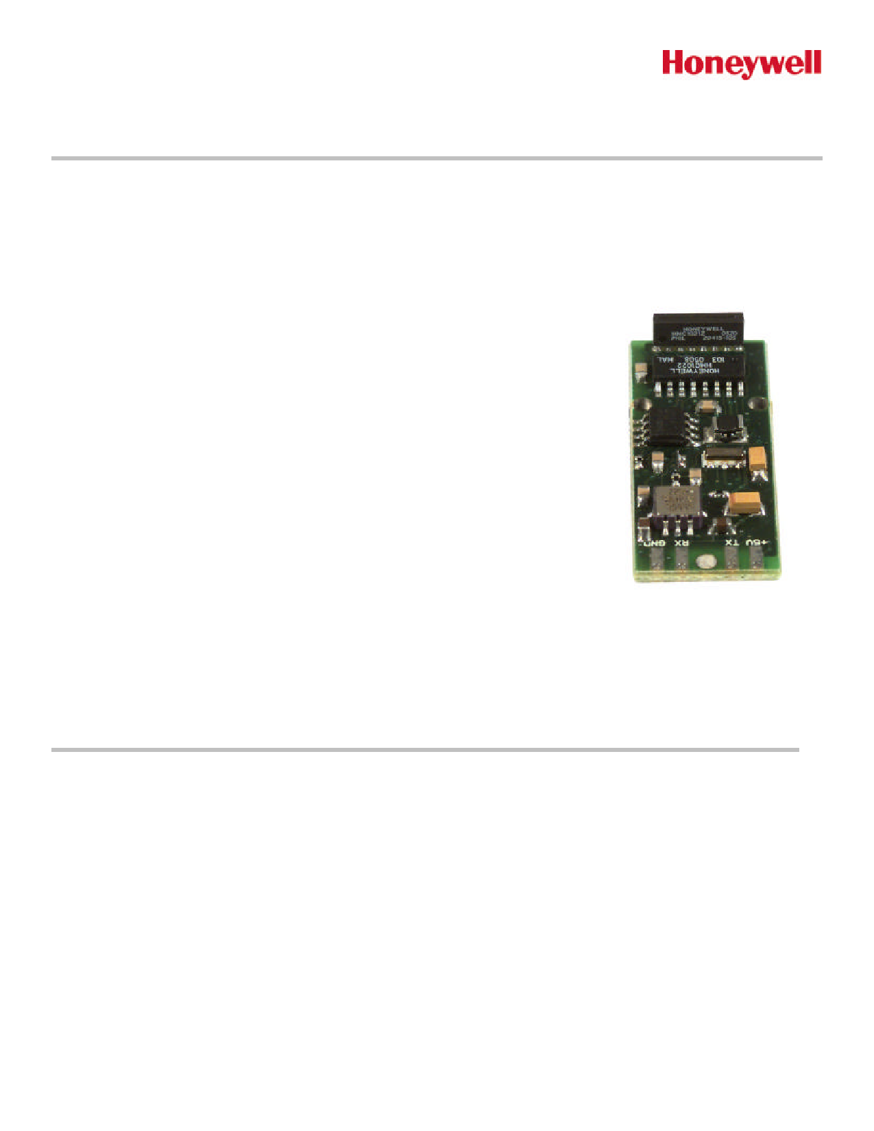
Digital Compass Solution
HMR3400
The Honeywell HMR3400 is a digital compass solution designed for use in navigation and precision pointing applications.
Honeywell’s magnetoresistive sensor technology is coupled with a MEMS accelerometer to provide a miniature, reliable
tilt-compensated electronic compass. Using a common set of commands from the legacy HMR3300 digital compass
solution, the HMR3400 is designed to be easily integrated into host systems with a regulated 5 volt supply and a UART
serial data interface.
The HMR3400 includes a MEMS accelerometer for a horizontal three -axis, tilt
compensated precision compass for performance up to a ±60° tilt range .
Honeywell continues to maintain product excellence and performance by introducing
innovative solid-state magnetic sensor solutions. These are highly reliable, top
performance products that are delivered when promised. Honeywell’s magnetic
sensor product s provide real solutions you can count on.
FEATURES
4 Compact Solution on a 0.6 by 1.5” PCB
4 Precision Compass Accuracy
4 Tilt-Compensated
4 -40° to +85°C Operating Temp Range
4 8 Hz Continuous Update Rate
4 Hard-Iron Compensation Routine
4 0.5° Repeatability
BENEFITS
4 Narrow Dimensions and Small Size for Tight Mounting Conditions,
Minimal Layout Constraints
4 ±1° at Level Heading Accuracy
4 Up to ±60° of Pitch and Roll Angles Using a MEMS Accelerometer
4 Consumer and Industrial Environment Uses
4 Rapid Heading Computations for Guidance Applications
4 User Driven Calibration to Null Stray Fields
4 Magnetoresistive Sensor Technology for Consistency
http://www.Datasheet4U.com
1 page 
HMR3400
should be ±200 ADC counts or less in these offset variables. Sending these Xof, Yof, and Zof values back to zero returns
the compass to the factory calibration state.
For the HMR3400, the above described level turns will calibrate the XY axis’, but the Z-axis should also be calibrated as
well One full rotation with as much pitch and roll variation included as application allows. If only mild pitch and roll
variations are possible, complete the level rotations, exit the calibration routine, and force the Zof value to zero. Some
accuracy maybe lost in this zeroing, but the mild tilt would likely never cause serious tilt-compensation heading error.
UART COMMUNICATION PROTOCOL
HMR3400 module communicates through ASCII characters with the * or # characters as start bytes. The data bit format
is 1 Start, 8 Data, 1 Stop, and No parity bits. Factory baud rate is set to 19,200. Asynchronous communication has the
complete menu of commands. Synchronous communication is limited to direct heading queries and no other commands.
POWER-ON/RESET
The compasses require a hard power-on transition on the power supply voltage to serve as an internal hardware reset
and clock-start. Some bench power supplies may create a soft-start condition and the HMR3400 my not react if not reset
suddenly. An in-line power supply switch (mechanical or electrical) may be required when prototyping to avoid soft-starts.
Upon application of power or after a Reset Command, the HMR3400 will run about an 800 milli-second initialization
routine to set the onboard hardware and grab EEPROM variables and shadow them in controller RAM locations for
operation.
INITIAL STATUS OUTPUT
The HMR3400 will begin sending ASCII characters immediately after the initialization routine ends. The first line of text will
be the model number of the compass and the internal firmware revision number. A second response string will be sent,
starting with a # character and either the N, W or A characters. The #N response indicates normal operation and is the
always expected response from the HMR3200. The #W and #A responses indicate the low temperature warning and
alarm environments had been encountered. These responses will be reset to normal when the user sends the pitch and
roll re-zero commands to re-calibrate the MEMS accelerometer for best tilt-compensation performance and accurate tilt
indications.
After initialization, the compasses automatically begin streaming heading or magnetometer output data at 8Hz. Users
must send a start/stop command (*S) to exit continuous streaming data, and to get the controller’s full attention to the next
commands.
OPERATIONAL COMMANDS
Syntax: *X<cr><lf>
Sends command for an operational mode change. The * prefix indicates command type.
A #I response indicates an invalid command was sent.
Heading Output Command
*H<cr><lf>
Selects the Heading output mode (factory set default). This configuration is saved in non-volatile memory. All data
are in decimal degrees.
Response Format: Heading, Pitch, Roll<cr><lf>
Eg: 123.4, 18.6, -0.5<cr><lf>
Magnetometer Output Command
*M<cr><lf>
www.honeywell.com
5
5 Page | ||
| Páginas | Total 9 Páginas | |
| PDF Descargar | [ Datasheet HMR3400.PDF ] | |
Hoja de datos destacado
| Número de pieza | Descripción | Fabricantes |
| HMR3400 | Digital Compass Solution | Honeywell Accelerometers |
| Número de pieza | Descripción | Fabricantes |
| SLA6805M | High Voltage 3 phase Motor Driver IC. |
Sanken |
| SDC1742 | 12- and 14-Bit Hybrid Synchro / Resolver-to-Digital Converters. |
Analog Devices |
|
DataSheet.es es una pagina web que funciona como un repositorio de manuales o hoja de datos de muchos de los productos más populares, |
| DataSheet.es | 2020 | Privacy Policy | Contacto | Buscar |