|
|
|
PDF M3G2803R305R4T Data sheet ( Hoja de datos )
| Número de pieza | M3G2803R305R4T | |
| Descripción | HIGH RELIABILITY RADIATION HARDENED DC-DC CONVERTER | |
| Fabricantes | IRF | |
| Logotipo | ||
Hay una vista previa y un enlace de descarga de M3G2803R305R4T (archivo pdf) en la parte inferior de esta página. Total 9 Páginas | ||
|
No Preview Available !
PD-97795
HIGH RELIABILITY RADIATION
HARDENED DC-DC CONVERTER
M3G2803R305R4T
28V Input, Triple Output
Description
The M3G-Series of DC-DC converters are radiation
hardened, high reliability converters designed for
extended operation in hostile environments. Their small
size and low weight make them ideal for applications
such as geostationary earth orbit satellites and deep
space probes. They exhibit a high tolerance to total
ionizing dose, single event effects and environmental
stresses such as temperature extremes, mechanical
shock, and vibration.
The converters incorporate a fixed frequency single
ended forward topology with magnetic feed back and
an internal EMI filter that utilizes metallized film capacitors
instead of large multilayer ceramic capacitors for
improved reliability. These converters are capable of
meeting the conducted emissions and conducted
susceptibility requirements of MIL-STD-461C without
any additional components. External inhibit and
synchronization input and output allow these converters
to be easily incorporated into larger power systems.
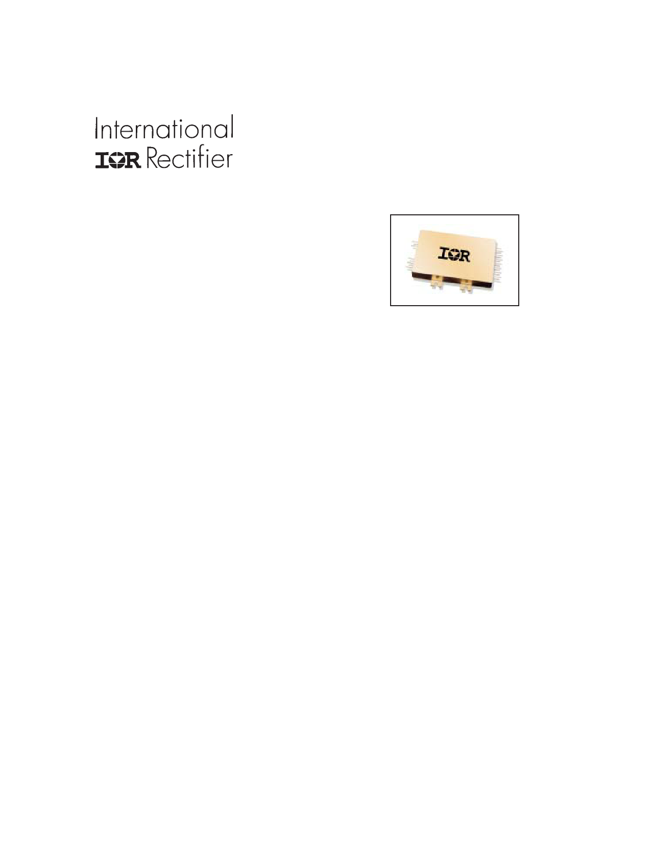
They are enclosed in a hermetic 3.5" x 2.5" x 0.475"
package constructed of an Aluminum/Silicon-Carbide
(Al/SiC) base and an Alloy 48 ring frame and they weigh
less than 110 grams. The package utilizes rugged ceramic
feed-through copper core pins and is sealed using
parallel seam welding.
Full environmental screening includes temperature
cycling, constant acceleration, fine and gross leak,
particle impact noise detection (PIND), radiographic and
320 hours burn-in.
Non-flight versions of the M3G-Series converters are
available for system development purposes. Variations
in electrical specifications and screening to meet custom
requirements can be accommodated.
Features
n Total Dose > 200 Krad(Si),
typically usable to > 1 Mrad(Si)
n SEE 82 MeV.cm2/mg
n Internal EMI Filter, converter capable of
meeting MIL-STD-461C CE03
n Low Weight, < 110 grams
n Magnetically Coupled Feedback
n 18V to 50V DC Input Range
n Up to 35W Output Power
n Main Output Isolated from Dual Outputs
n High Efficiency - to 75%
n -55°C to +125°C Operating Temperature Range
n 100MΩ @ 500VDC Isolation
n Under-Voltage Lockout
n Synchronization Input and Output
n Short Circuit and Overload Protection
n Output Over Voltage Limiter
n External Inhibit
n > 5,000,000 Hour MTBF
Applications
n Geostationary Earth Orbit Satellites (GEO)
n Deep Space Satellites / Probes
n Strategic Weapons and Communication
Systems
www.irf.com
1
08/24/12
http://www.Datasheet4U.com
1 page 
M3G2803R305R4T
Table I. Electrical Performance Characteristics - notes
1. Parameter is tested as part of design characterization or after design changes. Thereafter, parameter
shall be guaranteed to the limits specified.
2. Parameter verified during line and load regulation tests.
3. Although operation with no load is permissible, light loading on the main output may cause the output
voltage of the auxiliary outputs to drop out of regulation. It is therefore recommended that at least 200 mA
or 20 percent of the total output power, whichever is greater, be taken from the main output.
4. Although operation with no load is permissible, heavy loading on the main output may cause the output
voltage of the auxiliary outputs to rise out of regulation. It is therefore recommended that at least 50 mA
or 20 percent of the total output power, whichever is greater, be taken from the auxiliary outputs.
5. Unless otherwise specified, “Rated” load is 17.5W on the main output and 8.75 watts each on the auxiliary
outputs.
6. Guaranteed for a D.C. to 20MHz bandwidth. Tested using a 20KHz to 10MHz bandwidth.
7. Capacitive load may be any value from 0 to the maximum limit without compromising dc performance. A
capacitive load in excess of the maximum limit may interfere with the proper operation of the converter’s
overload protection, causing erratic behavior during turn-on.
8. Overload power dissipation is defined as the device power dissipation with the load set such that VOUT =
90% of nominal.
9. Load step transition time ≥ 10 µsec.
10. Recovery time is measured from the initiation of the transient to where VOUT has returned to within ±1%
of its steady state value.
11. Line step transition time ≥ 100 µsec.
12. Turn-on delay time from either a step application of input power or a logic low to a logic high transition on
the inhibit pin (pin 3) to the point where VOUT = 90% of nominal.
13. Load is varied for output under test while the remaining outputs are loaded at 50% of rated. Regulation
relative to output voltage at 50% rated load.
14. Although operation at temperatures between +85°C and +125°C is guaranteed, no parameter limits are
specified.
Radiation Performance Characteristics
Test Inspection
Method
Min Typ
Unit
MIL-PRF-883, Method 1019
Total Ionizing Dose (Gamma) Operating bias applied during exposure,
Dose Rate (Gamma Dot)
Full Rated Load, VIN = 28V
MIL-STD-883, Method 1023
200
Temporary Saturation Operating bias applied during exposure,
Survival
Full Rated Load, VIN = 28V
1E8
4E10
Neutron Fluence
MIL-STD-883, Method 1017
8E12
Heavy Ions (LET)
Single Event Effects
Operating bias applied during exposure,
SEU, SEL, SEGR, SEB
Full Rated Load, VIN = 28V
Test lab: Brookhaven National Laboratory,
82
Tandem Van de Graaff Generator
300
1E11
1E13
Krads(Si)
Rads(Si)/sec
Neutrons/cm2
MeVxcm2/mg
International Rectifier currently does not have a DLA Land and Maritime certified Radiation Hardness
Assurance Program
www.irf.com
5
http://www.Datasheet4U.com
5 Page | ||
| Páginas | Total 9 Páginas | |
| PDF Descargar | [ Datasheet M3G2803R305R4T.PDF ] | |
Hoja de datos destacado
| Número de pieza | Descripción | Fabricantes |
| M3G2803R305R4T | HIGH RELIABILITY RADIATION HARDENED DC-DC CONVERTER | IRF |
| Número de pieza | Descripción | Fabricantes |
| SLA6805M | High Voltage 3 phase Motor Driver IC. |
Sanken |
| SDC1742 | 12- and 14-Bit Hybrid Synchro / Resolver-to-Digital Converters. |
Analog Devices |
|
DataSheet.es es una pagina web que funciona como un repositorio de manuales o hoja de datos de muchos de los productos más populares, |
| DataSheet.es | 2020 | Privacy Policy | Contacto | Buscar |