|
|
|
PDF A4953 Data sheet ( Hoja de datos )
| Número de pieza | A4953 | |
| Descripción | (A4952 / A4953) Full-Bridge DMOS PWM Motor Drivers | |
| Fabricantes | Allegro | |
| Logotipo | ||
Hay una vista previa y un enlace de descarga de A4953 (archivo pdf) en la parte inferior de esta página. Total 11 Páginas | ||
|
No Preview Available !
A4952 and A4953
Full-Bridge DMOS PWM Motor Drivers
Features and Benefits
• Low RDS(on) outputs
• Overcurrent protection (OCP)
▫ Motor short protection
▫ Motor lead short to ground protection
▫ Motor lead short to battery protection
• Low Power Standby mode
• Adjustable PWM current limit
• Synchronous rectification
• Internal undervoltage lockout (UVLO)
• Crossover-current protection
• Fault output (A4952 only)
• Selectable retry (A4952 only)
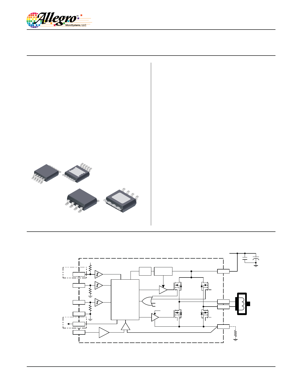
Packages:
10-pin MSOP
with exposed thermal pad
(LY package)
Description
Designed for pulse width modulated (PWM) control of DC
motors, the A4952 and A4953 are capable of peak output
currents to ±2 A and operating voltages to 40 V.
Input terminals are provided for use in controlling the speed and
direction of a DC motor with externally applied PWM control
signals. Internal synchronous rectification control circuitry is
provided to lower power dissipation during PWM operation.
Internal circuit protection includes overcurrent protection,
motor lead short to ground or supply, thermal shutdown with
hysteresis, undervoltage monitoring of VBB, and crossover-
current protection.
The A4952 is provided in a low-profile 10-pin MSOP package
(suffix LY) and the A4953 is provided in a low-profile
8-pin SOICN package (suffix LJ). Both packages have an
exposed thermal pad, and are lead (Pb) free, with 100% matte tin
leadframe plating.
8-pin SOICN
with exposed thermal pad
(LJ package)
Not to scale
Functional Block Diagram
A4952 only
RTRY
VINT
IN1
IN2
GND
A4952 only
FLTn
VREF
÷ 10
OSC
Charge
Pump
Control
Logic
Disable
TSD
UVLO
7V
Load Supply
VBB
OUT1
OUT2
LSS
(Optional)
A4952-DS, Rev. 2
Free Datasheet http://www.Datasheet4U.com
1 page 
A4952 and
A4953
Full-Bridge DMOS PWM Motor Drivers
Functional Description
Device Operation
The A4952 and A4953 are designed to operate DC motors. The
output drivers are all low-RDS(on) , N-channel DMOS drivers
that feature internal synchronous rectification to reduce power
dissipation. The current in the output full bridge is regulated with
fixed off-time pulse width modulated (PWM) control circuitry.
The IN1 and IN2 inputs allow two-wire control for the bridge.
Protection circuitry includes internal thermal shutdown, and pro-
tection against shorted loads, or against output shorts to ground
or supply. Undervoltage lockout prevents damage by keeping the
outputs off until the driver has enough voltage to operate nor-
mally.
Standby Mode
Low Power Standby mode is activated when both input (INx)
pins are low for longer than 1 ms. Low Power Standby mode
disables most of the internal circuitry, including the charge pump
and the regulator. When the A4952/A4953 is coming out of
standby mode, the charge pump should be allowed to reach its
regulated voltage (a maximum delay of 200 μs) before any PWM
commands are issued to the device.
Internal PWM Current Control
Initially, a diagonal pair of source and sink FET outputs are
enabled and current flows through the motor winding and the
optional external current sense resistor, RS. When the voltage
across RS equals the comparator trip value, then the current sense
comparator resets the PWM latch. The latch then turns off the
sink and source FETs (Mixed Decay mode).
VREF
The maximum value of current limiting is set by the selection of
RSx and the voltage at the VREF pin. The transconductance func-
tion is approximated by the maximum value of current limiting,
ITripMAX (A), which is set by:
ITripMAX =
VREF
AV RS
where VREF is the input voltage on the VREF pin (V) and RS is
the resistance of the sense resistor (Ω) on the LSS terminal.
Overcurrent Protection
In the A4952, a current monitor will protect the IC from damage
due to output shorts. The internal Overcurrent Protection (OCP)
has the following features:
• Fault Output (FLTn pin). If a short is detected, the open drain
FLTn output signal goes low.
• Retry Input (RTRY pin). Sets the action taken by the IC to re-
spond to an OCP fault. If the RTRY pin is tied to GND, then the
outputs will be turned-on again after a 2-ms timeout, to check
if a fault condition remains. If the RTRY pin is left open, then
the fault will be latched, and the IC will disable the outputs. The
fault latch can only be cleared by coming out of Low Power
Standby mode or by cycling the power to VBB.
Note: The A4953 overcurrent protection behaves in the same
manner but the fault is latched and can only be reset by putting
the device into standby mode or by cycling the power to VBB.
During OCP events, Absolute Maximum Ratings may be
exceeded for a short period of time before the device latches.
Shutdown
If the die temperature increases to approximately 160°C, the full
bridge outputs will be disabled until the internal temperature falls
below a hysteresis, TTSDhys , of 20°C. Internal UVLO is present
on VBB to prevent the output drivers from turning-on below the
UVLO threshold.
Braking
The braking function is implemented by driving the device in
Slow Decay mode, which is done by applying a logic high to both
inputs, after a bridge-enable Chop command (see PWM Control
Truth Table). Because it is possible to drive current in both direc-
tions through the DMOS switches, this configuration effectively
shorts-out the motor-generated BEMF, as long as the Chop com-
mand is asserted. The maximum current can be approximated by
VBEMF / RL. Care should be taken to ensure that the maximum
ratings of the device are not exceeded in worse case braking situ-
ations: high speed and high-inertia loads.
Allegro MicroSystems, LLC
115 Northeast Cutoff
Worcester, Massachusetts 01615-0036 U.S.A.
1.508.853.5000; www.allegromicro.com
5
Free Datasheet http://www.Datasheet4U.com
5 Page 
A4952 and
A4953
Full-Bridge DMOS PWM Motor Drivers
Revision History
Revision
Rev. 2
Revision Date
August 6, 2012
Description of Revision
Update PWM table
Copyright ©2010-2013, Allegro MicroSystems, LLC
Allegro MicroSystems, LLC reserves the right to make, from time to time, such departures from the detail specifications as may be required to
permit improvements in the performance, reliability, or manufacturability of its products. Before placing an order, the user is cautioned to verify that
the information being relied upon is current.
Allegro’s products are not to be used in life support devices or systems, if a failure of an Allegro product can reasonably be expected to cause the
failure of that life support device or system, or to affect the safety or effectiveness of that device or system.
The information included herein is believed to be accurate and reliable. However, Allegro MicroSystems, LLC assumes no responsibility for its
use; nor for any infringement of patents or other rights of third parties which may result from its use.
For the latest version of this document, visit our website:
www.allegromicro.com
Allegro MicroSystems, LLC
115 Northeast Cutoff
Worcester, Massachusetts 01615-0036 U.S.A.
1.508.853.5000; www.allegromicro.com
11
Free Datasheet http://www.Datasheet4U.com
11 Page | ||
| Páginas | Total 11 Páginas | |
| PDF Descargar | [ Datasheet A4953.PDF ] | |
Hoja de datos destacado
| Número de pieza | Descripción | Fabricantes |
| A4950 | Full-Bridge DMOS PWM Motor Driver | Allegro MicroSystems |
| A4952 | (A4952 / A4953) Full-Bridge DMOS PWM Motor Drivers | Allegro |
| A4953 | (A4952 / A4953) Full-Bridge DMOS PWM Motor Drivers | Allegro |
| Número de pieza | Descripción | Fabricantes |
| SLA6805M | High Voltage 3 phase Motor Driver IC. |
Sanken |
| SDC1742 | 12- and 14-Bit Hybrid Synchro / Resolver-to-Digital Converters. |
Analog Devices |
|
DataSheet.es es una pagina web que funciona como un repositorio de manuales o hoja de datos de muchos de los productos más populares, |
| DataSheet.es | 2020 | Privacy Policy | Contacto | Buscar |