|
|
|
PDF FNB41560 Data sheet ( Hoja de datos )
| Número de pieza | FNB41560 | |
| Descripción | Smart Power Module | |
| Fabricantes | Fairchild Semiconductor | |
| Logotipo | ||
Hay una vista previa y un enlace de descarga de FNB41560 (archivo pdf) en la parte inferior de esta página. Total 15 Páginas | ||
|
No Preview Available !
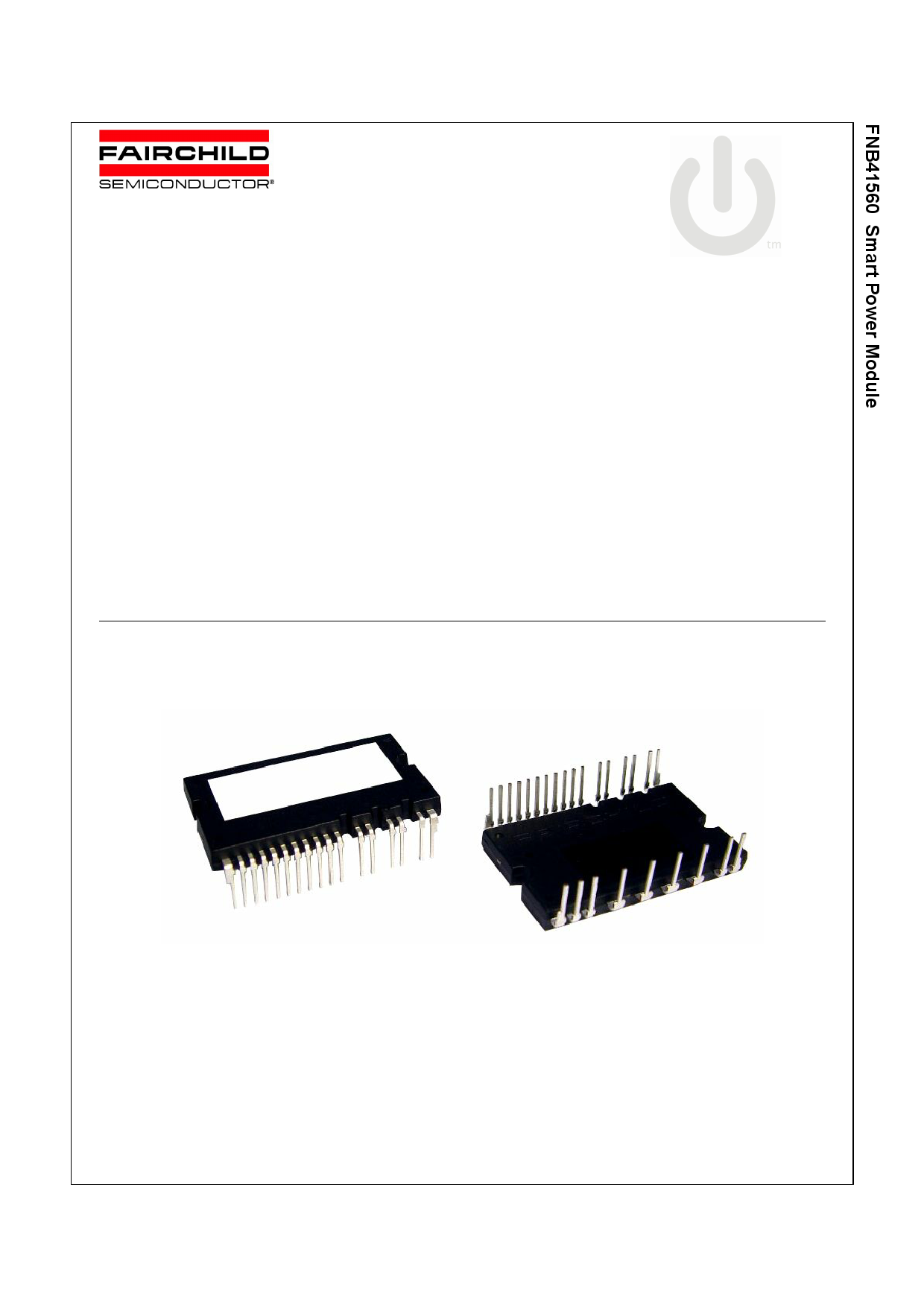
FNB41560
Smart Power Module
January 2010
Motion-SPMTM
Features
• 600V-15A 3-phase IGBT inverter bridge including control ICs
for gate driving and protection
• Easy PCB layout due to built-in bootstrap diode and VS out-
put
• Divided negative dc-link terminals for inverter current sensing
applications
• Single-grounded power supply due to built-in HVIC
• Built-in thermistor for over-temperature monitoring
• Isolation rating of 2000Vrms/min.
Applications
• AC 100V ~ 253V three-phase inverter drive for small power
ac motor drives
• Home appliances applications like air conditioner and wash-
ing machine
General Description
It is an advanced motion-smart power module (Motion-SPMTM)
that Fairchild has newly developed and designed to provide
very compact and high performance ac motor drives mainly tar-
geting low-power inverter-driven application like air conditioner
and washing machine. It combines optimized circuit protection
and drive matched to low-loss IGBTs. System reliability is fur-
ther enhanced by the integrated under-voltage lock-out protec-
tion, short-circuit protection, and temperature monitoring. The
high speed built-in HVIC provides opto-coupler-less single-sup-
ply IGBT gate driving capability that further reduce the overall
size of the inverter system design. Each phase current of
inverter can be monitored separately due to the divided nega-
tive dc terminals.
Additional Information
For further infomation, please see AN-9070 and FEB306-001 in
http://www.fairchildsemi.com
Figure 1.
©2010 Fairchild Semiconductor Corporation
FNB41560 Rev. C
1
www.fairchildsemi.com
Free Datasheet http://www.Datasheet4U.com
1 page 
Absolute Maximum Ratings (TJ = 25°C, Unless Otherwise Specified)
Inverter Part
Symbol
Parameter
Conditions
VPN
VPN(Surge)
VCES
IO,25
IO,100
Ipk
PC
TJ
Supply Voltage
Supply Voltage (Surge)
Collector-emitter Voltage
Output Phase Current
Output Phase Current
Output Peak Phase Current
Collector Dissipation
Operating Junction Temperature
Applied between P- NU, NV, NW
Applied between P- NU, NV, NW
TC = 25°C, TJ < 150°C (Note 1)
TC = 100°C, TJ < 150°C (Note 1)
TC = 25°C, TJ < 150°C, Under 1ms Pulse Width
TC = 25°C per One Chip
(Note 2)
Note:
1. Sinusoidal PWM at VPN=300V, VCC=VBS=15V, TJ < 150°℃, FSW=20kHz, MI=0.9, PF=0.8
2. The maximum junction temperature rating of the power chips integrated within the SPM is 150°C.
Rating
450
500
600
15
7.5
22
34
-40 ~ 150
Control Part
Symbol
Parameter
VCC Control Supply Voltage
VBS High-side Control Bias
Voltage
VIN Input Signal Voltage
VFO Fault Output Supply Voltage
IFO Fault Output Current
VSC Current Sensing Input Voltage
Conditions
Rating
Applied between VCC(H), VCC(L) - COM
20
Applied between VB(U) - VS(U), VB(V) - VS(V),
VB(W) - VS(W)
20
Applied between IN(UH), IN(VH), IN(WH), IN(UL), -0.3~VCC+0.3
IN(VL), IN(WL) - COM
Applied between VFO - COM
-0.3~VCC+0.3
Sink Current at VFO Pin
1
Applied between CSC - COM
-0.3~VCC+0.3
Units
V
V
V
A
A
A
W
°C
Units
V
V
V
V
mA
V
Bootstrap Diode Part
Symbol
Parameter
Conditions
VRRM
IF
IFP
TJ
Maximum Repetitive Reverse Voltage
Forward Current
Forward Current (Peak)
Operating Junction Temperature
TC = 25°C
TC = 25°C, Under 1ms Pulse Width
Rating
600
0.5
1
-40 ~ 150
Units
V
A
A
°C
Total System
Symbol
Parameter
VPN(PROT) Self Protection Supply Voltage Limit
(Short Circuit Protection Capability)
TSTG
VISO
Storage Temperature
Isolation Voltage
Conditions
VCC = VBS = 13.5 ~ 16.5V
TJ = 150°C, Non-repetitive, less than 2ms
60Hz, Sinusoidal, AC 1 minute, Connection Pins
to heat sink plate
Rating
400
-40 ~ 125
2000
Units
V
°C
Vrms
Thermal Resistance
Symbol
Parameter
Conditions
Rth(j-c)Q
Rth(j-c)F
Junction to Case Thermal
Resistance
Inverter IGBT part (per 1/6 module)
Inverter FWD part (per 1/6 module)
Note:
3. For the measurement point of case temperature(TC), please refer to Figure 2.
Min.
-
-
Typ.
-
-
Max.
3.6
4.8
Units
°C/W
°C/W
FNB41560 Rev. C
5 www.fairchildsemi.com
Free Datasheet http://www.Datasheet4U.com
5 Page 
Time Charts of SPMs Protective Function
Input Signal
Protection
Circuit State
Control
Supply Voltage
RESET
SET
UVCCR
a1
UVCCD
a2
a3
a4
RESET
a6
a7
Output Current
Fault Output Signal
a5
a1 : Control supply voltage rises: After the voltage rises UVCCR, the circuits start to operate when next input is applied.
a2 : Normal operation: IGBT ON and carrying current.
a3 : Under voltage detection (UVCCD).
a4 : IGBT OFF in spite of control input condition.
a5 : Fault output operation starts.
a6 : Under voltage reset (UVCCR).
a7 : Normal operation: IGBT ON and carrying current.
Figure 11. Under-Voltage Protection (Low-side)
Input Signal
Protection
Circuit State
Control
Supply Voltage
RESET
UVBSR
b1
UVBSD
b2
SET
b3
b4
RESET
b5
b6
Output Current
High-level (no fault output)
Fault Output Signal
b1 : Control supply voltage rises: After the voltage reaches UVBSR, the circuits start to operate when next input is applied.
b2 : Normal operation: IGBT ON and carrying current.
b3 : Under voltage detection (UVBSD).
b4 : IGBT OFF in spite of control input condition, but there is no fault output signal.
b5 : Under voltage reset (UVBSR)
b6 : Normal operation: IGBT ON and carrying current
Figure 12. Under-Voltage Protection (High-side)
FNB41560 Rev. C
11 www.fairchildsemi.com
Free Datasheet http://www.Datasheet4U.com
11 Page | ||
| Páginas | Total 15 Páginas | |
| PDF Descargar | [ Datasheet FNB41560.PDF ] | |
Hoja de datos destacado
| Número de pieza | Descripción | Fabricantes |
| FNB41560 | Motion SPM 45 Series | Fairchild Semiconductor |
| FNB41560 | Smart Power Module | Fairchild Semiconductor |
| FNB41560B2 | Motion SPM 45 Series | Fairchild Semiconductor |
| Número de pieza | Descripción | Fabricantes |
| SLA6805M | High Voltage 3 phase Motor Driver IC. |
Sanken |
| SDC1742 | 12- and 14-Bit Hybrid Synchro / Resolver-to-Digital Converters. |
Analog Devices |
|
DataSheet.es es una pagina web que funciona como un repositorio de manuales o hoja de datos de muchos de los productos más populares, |
| DataSheet.es | 2020 | Privacy Policy | Contacto | Buscar |