|
|
|
PDF NMG1215SC Data sheet ( Hoja de datos )
| Número de pieza | NMG1215SC | |
| Descripción | Isolated 2W Single Output DC/DC Converters | |
| Fabricantes | Murata | |
| Logotipo | ||
Hay una vista previa y un enlace de descarga de NMG1215SC (archivo pdf) en la parte inferior de esta página. Total 7 Páginas | ||
|
No Preview Available !
www.murata-ps.com
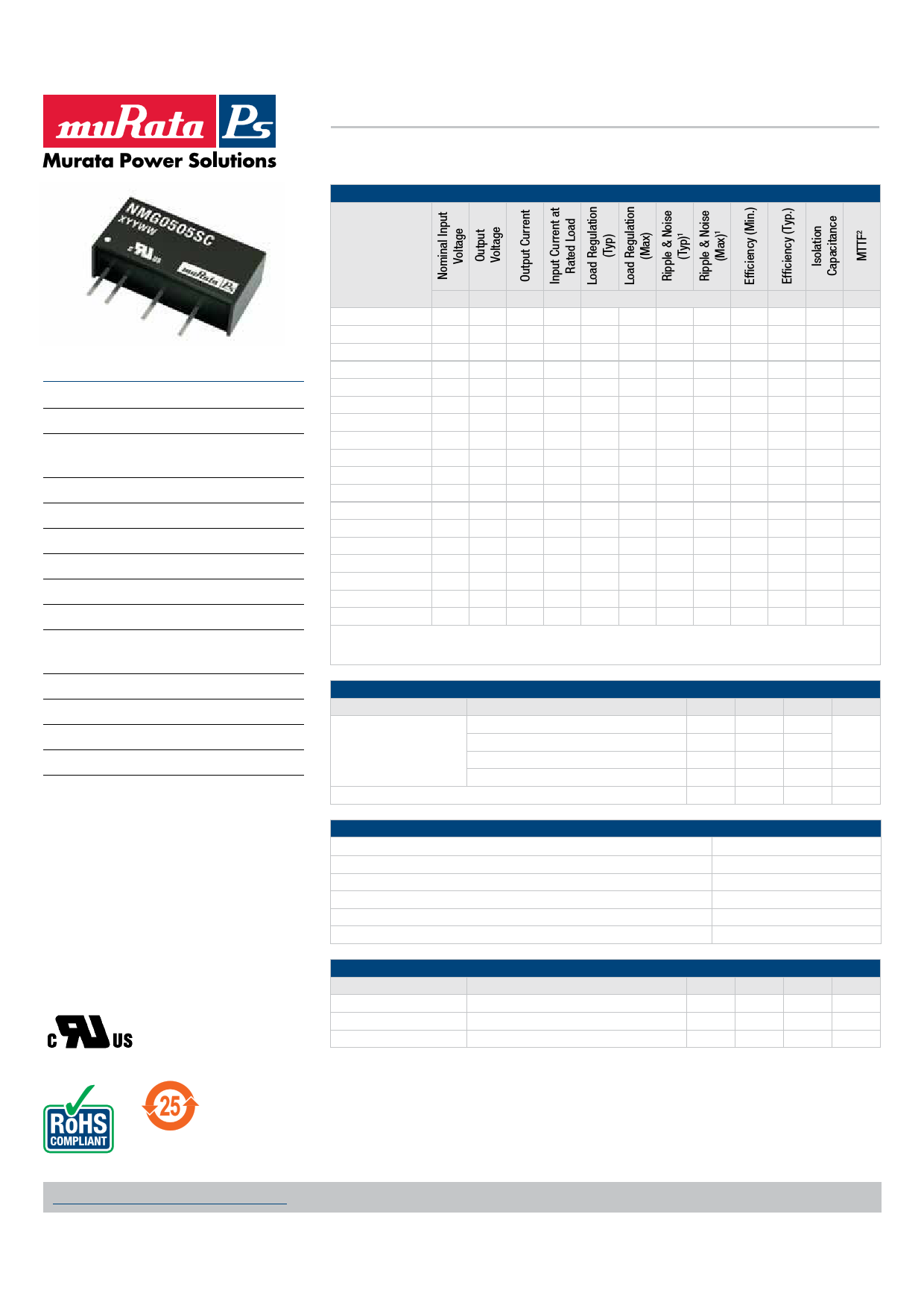
SELECTION GUIDE
NMG Series
Isolated 2W Single Output DC/DC Converters
Order Code
FEATURES
UL 60950 recognised
Efficiency from 80%
Wide temperature performance at full
2 Watt load, –40°C to 85°C
UL 94V-0 package material
Industry standard pinout
1kVDC isolation
5V, 12V, 15V & 24V input
5V, 9V, 12V, & 15V output
Internal SMD construction
Fully encapsulated with toroidal
magnetics
No external components required
MTTF up to 3.9 million hours
Pin compatible with NMR series
No electrolytic or tantalum capacitors
PRODUCT OVERVIEW
The NMG series of DC/DC Converters is
particularly suited to isolating and/or converting
DC power rails. The galvanic isolation allows the
device to be configured to provide an isolated
negative rail in systems where only positive rails
exist. The wide temperature range guarantees
startup from –40°C and full 2 watt output at 85°C.
Pin compatibility with the NMR and MER1 series
ensures ease of upgradeability.
V V mA mA
%
mVp-p
% % pF kHrs
NMG0505SC
5 5 400 470 5.7 7.3 28 35 81 83 33 3956
NMG0509SC
5 9 222 455 4.2 5.9 20 25 84 86.5 40 3682
NMG0512SC
5 12 167 450 3.8 5.1 18 25 84 87.5 40 3299
NMG0515SC
5 15 133 450 3.4 4.5 16 25 84 87.5 40 2833
NMG0524SC
5 24 83 465 4.3 6 35 60 82 85 35 2189
NMG1205SC
12 5 400 200 4.2 4.9 22 35 81 83.5 40 2519
NMG1209SC
12 9 222 190 2.6 3.1 16 25 83 87 61 2405
NMG1212SC
12 12 167 190 2.4 2.9 13 25 85 88 74 2235
NMG1215SC
12 15 133 185 2.0 2.4 12 25 85 88 68 2011
NMG1224SC
12 24 83 190 2.6 4 25 40 84 86.5 60 2189
NMG1505SC
15 5 400 160 4.3 6 40 60 80 83 40 3963
NMG1509SC
15 9 222 155 2.9 4.5 25 40 82 86.5 55 3176
NMG1512SC
15 12 167 150 2.4 3.5 25 40 84 87.5 65 2875
NMG1515SC
15 15 133 150 2.3 3.5 25 40 84 88 75 2483
NMG2405SC
24 5 400 100 4.1 6 40 70 80 84 45 3659
NMG2409SC
24 9 222 95 2.6 4 30 50 84 87.5 55 2496
NMG2412SC
24 12 167 95 2.1 3.5 25 50 84 88 75 3824
NMG2415SC
24 15 133 95 2 3.5 30 50 85 88.5 85 3500
When operated with additional external load capacitance the rise time of the input voltage will determine the maximum external
capacitance value for guaranteed start up. The slower the rise time of the input voltage the greater the maximum value of the
additional external capacitance for reliable start up.
INPUT CHARACTERISTICS
Parameter
Conditions
Continuous operation, 5V input types
Voltage range
Continuous operation, 12V input types
Continuous operation, 15V input types
Continuous operation, 24V input types
Reflected ripple current
Min. Typ. Max. Units
4.5 5 5.5
10.8 12 13.2
V
13.5 15 16.5
21.6 24 26.4
7.5 15 mA p-p
ABSOLUTE MAXIMUM RATINGS
Lead temperature 1.5mm from case for 10 seconds
Internal power dissipation
Input voltage VIN, NMG05 types
Input voltage VIN, NMG12 types
Input voltage VIN, NMG15 types
Input voltage VIN, NMG24 types
260°C
550mW
7V
15V
18V
28V
OUTPUT CHARACTERISTICS
Parameter
Conditions
Rated Power
TA=-40°C to 85°C
Voltage Set Point Accuracy See tolerance envelope
Line regulation
High VIN to low VIN
Min. Typ.
1.05
1. See Ripple & Noise characterisation method.
2. Calculated using MIL-HDBK-217F FN2 with nominal input voltage at full load.
All specifications typical at TA=25°C, nominal input voltage and rated output current unless otherwise specified.
Max.
2
1.2
Units
W
%/%
For full details go to
www.murata-ps.com/rohs
www.murata-ps.com/support
KDC_NMG.E01 Page 1 of 7
Free Datasheet http://www.datasheetlist.com/
1 page 
NMG Series
Isolated 2W Single Output DC/DC Converters
APPLICATION NOTES (continued)
Output Ripple Reduction
By using the values of inductance and capacitance stated, the output ripple at the rated load is lowered to 5mV p-p max.
Component selection
Capacitor: It is required that the ESR (Equivalent Series Resistance) should be as low as possible, ceramic types are recommended.
The voltage rating should be at least twice (except for 15V output), the rated output voltage of the DC/DC converter.
Inductor: The rated current of the inductor should not be less than that of the output of the DC/DC converter. At the rated current, the DC resistance of the inductor
should be such that the voltage drop across the inductor is <2% of the rated voltage of the DC/DC converter. The SRF (Self Resonant Frequency) should be
>20MHz.
L
Power
Source
DC
DC
C Load
NMG0505SC
NMG0509SC
NMG0512SC
NMG0515SC
NMG1205SC
NMG1209SC
NMG1212SC
NMG1215SC
L, μH
10
22
47
47
10
22
47
47
Inductor
SMD
82103C
82223C
82473C
82473C
82103C
82223C
82473C
82473C
Through Hole
11R103C
11R223C
11R473C
11R473C
11R103C
11R223C
11R473C
11R473C
Capacitor
C, μF
4.7
2.2
1
1
4.7
2.2
1
1
www.murata-ps.com/support
KDC_NMG.E01 Page 5 of 7
Free Datasheet http://www.datasheetlist.com/
5 Page | ||
| Páginas | Total 7 Páginas | |
| PDF Descargar | [ Datasheet NMG1215SC.PDF ] | |
Hoja de datos destacado
| Número de pieza | Descripción | Fabricantes |
| NMG1215SC | Isolated 2W Single Output DC/DC Converters | Murata |
| Número de pieza | Descripción | Fabricantes |
| SLA6805M | High Voltage 3 phase Motor Driver IC. |
Sanken |
| SDC1742 | 12- and 14-Bit Hybrid Synchro / Resolver-to-Digital Converters. |
Analog Devices |
|
DataSheet.es es una pagina web que funciona como un repositorio de manuales o hoja de datos de muchos de los productos más populares, |
| DataSheet.es | 2020 | Privacy Policy | Contacto | Buscar |