|
|
|
PDF LD7576 Data sheet ( Hoja de datos )
| Número de pieza | LD7576 | |
| Descripción | Green-Mode PWM Controller | |
| Fabricantes | Leadtrend | |
| Logotipo | ||
Hay una vista previa y un enlace de descarga de LD7576 (archivo pdf) en la parte inferior de esta página. Total 20 Páginas | ||
|
No Preview Available !
LD7576/76H/76J/76K
12/5/2007
Green-Mode PWM Controller with High-Voltage
Start-Up Circuit and Adjustable OLP Delay Time
REV. 03
General Description
The LD7576X series bring high performance, combines with
highly integrated functions, protections and EMI-improve
solution. It’s an ideal solution for those cost-sensitive system,
reducing component count and overall system cost.
The LD7576X series features near-lossless high voltage
startup circuit, green-mode power-saving operation,
leading-edge blanking of the current sensing and internal
slope compensation. They also consist with more
protections of OLP (Over Load Protection), OVP (Over
Voltage Protection) and OTP (Over Temperature Protection)
to prevent the circuit damage under abnormal conditions.
The LD7576X series are available in DIP-8 and SOP-8
package.
Features
z High-Voltage (500V) Startup Circuit
z Current Mode Control
z Non-Audible-Noise Green Mode Control
z UVLO (Under Voltage Lockout)
z LEB (Leading-Edge Blanking) on CS Pin
z Internal Slope Compensation
z OVP (Over Voltage Protection) on Vcc
z On-Chip OTP (Over Temperature Protection)
z OLP (Over Load Protection)
z Latch Mode Protection by CT pin
z 500mA Driving Capability
z Adjustable OLP delay time
Applications
z Switching AC/DC Adaptor and Battery Charger
z Open Frame Switching Power Supply
z LCD Monitor/TV Power
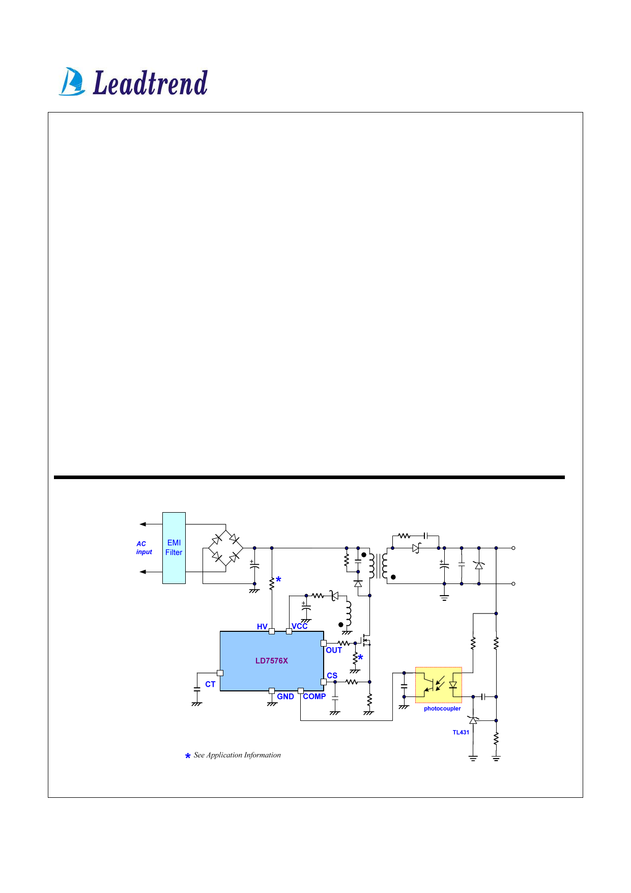
Typical Application
Leadtrend Technology Corporation
LD7576-DS-03 December 2007
1
www.leadtrend.com.tw
Free Datasheet http://www.datasheet4u.net/
1 page 
LD7576/76H/76J/76K
Absolute Maximum Ratings
Supply Voltage VCC
High-Voltage Pin, HV
COMP, CT, CS
Junction Temperature
Operating Ambient Temperature
Storage Temperature Range
Package Thermal Resistance (SOP-8)
Package Thermal Resistance (DIP-8)
Power Dissipation (SOP-8, at Ambient Temperature = 85°C)
Power Dissipation (DIP-8, at Ambient Temperature = 85°C)
Lead temperature (Soldering, 10sec)
ESD Voltage Protection, Human Body Model (except HV Pin)
ESD Voltage Protection, Machine Model
Gate Output Current
30V
-0.3V~600V
-0.3 ~7V
150°C
-40°C to 85°C
-65°C to 150°C
160°C/W
100°C/W
400mW
650mW
260°C
3KV
300V
500mA
Caution:
Stresses beyond the ratings specified in “Absolute Maximum Ratings” may cause permanent damage to the device. This is a stress only
rating and operation of the device at these or any other conditions above those indicated in the operational sections of this specification is not
implied.
Recommended Operating Conditions
Item
Supply Voltage VCC
VCC Capacitor
CT Value
COMP Pin Capacitor
Min.
11
10
0.047
1
Max.
25
47
0.1
100
Unit
V
μF
μF
nF
Leadtrend Technology Corporation
LD7576-DS-03 December 2007
5
www.leadtrend.com.tw
Free Datasheet http://www.datasheet4u.net/
5 Page 
and achieve regulation. The LD7576X series detects the
primary MOSFET current from the CS pin, which is not only
for the peak current mode control but also for the
pulse-by-pulse current limit. The maximum voltage
threshold of the current sensing pin is set at 0.85V. Thus the
MOSFET peak current can be calculated as:
IPEAK(MAX)
=
0.85V
RS
A 230nS leading-edge blanking (LEB) time is provided in the
input of CS pin to prevent false-triggering from the current
spike. In the low power applications, if the total pulse width
of the turn-on spikes is less than 230nS and the negative
spike on the CS pin does not exceed -0.3V, the R-C filter (as
shown in figure15) can be eliminated.
However, the total pulse width of the turn-on spike is related
to the output power, circuit design and PCB layout. It is
strongly recommended to add a small R-C filter (as shown in
figure 16) for higher power application to avoid the CS pin
from being damaged by the negative turn-on spike.
Output Stage and Maximum Duty-Cycle
An output stage of a CMOS buffer, with typical 500mA
driving capability, is incorporated to drive a power MOSFET
directly. And the maximum duty-cycle of LD7576X series
are limited to 75% to avoid the transformer saturation.
Voltage Feedback Loop
The voltage feedback signal is provided from the TL431 on
the secondary side through the photo-coupler to the COMP
pin of LD7576X series. The input stage of LD7576X series,
like the UC384X, is with 2 diodes voltage offset to feed the
voltage divider with 1/3 ratio, that is,
V+ (PWM COMPARATOR
)
=
1
3
× (VCOMP
−
2VF )
A pull-high resistor is embedded internally to optimize the
external circuit. Generally, an external capacitor in parallel
to photo-coupler is required in application.
LD7576/76H/76J/76K
VCC
OUT
LD7576X
CS
GND
230ns
blanking
time
Can be removed if the negative
spike is not over spec. (-0.3V).
Fig. 15
Fig. 16
Oscillator and Switching Frequency
The switching frequency of LD7576X series are fixed at
65KHz and 100KHz internally to provide the optimized
Leadtrend Technology Corporation
LD7576-DS-03 December 2007
11
www.leadtrend.com.tw
Free Datasheet http://www.datasheet4u.net/
11 Page | ||
| Páginas | Total 20 Páginas | |
| PDF Descargar | [ Datasheet LD7576.PDF ] | |
Hoja de datos destacado
| Número de pieza | Descripción | Fabricantes |
| LD7575 | Green-Mode PWM Controller | Leadtrend |
| LD7575A | Green-Mode PWM Controller | Leadtrend |
| LD7575B | Green-Mode PWM Controller | Leadtrend |
| LD7576 | Green-Mode PWM Controller | Leadtrend |
| Número de pieza | Descripción | Fabricantes |
| SLA6805M | High Voltage 3 phase Motor Driver IC. |
Sanken |
| SDC1742 | 12- and 14-Bit Hybrid Synchro / Resolver-to-Digital Converters. |
Analog Devices |
|
DataSheet.es es una pagina web que funciona como un repositorio de manuales o hoja de datos de muchos de los productos más populares, |
| DataSheet.es | 2020 | Privacy Policy | Contacto | Buscar |