|
|
|
PDF HFBR1412M Data sheet ( Hoja de datos )
| Número de pieza | HFBR1412M | |
| Descripción | Low Cost/ Miniature Fiber Optic Components with ST/ SMA/ SC and FC Ports | |
| Fabricantes | Agilent(Hewlett-Packard) | |
| Logotipo | ||
Hay una vista previa y un enlace de descarga de HFBR1412M (archivo pdf) en la parte inferior de esta página. Total 31 Páginas | ||
|
No Preview Available !
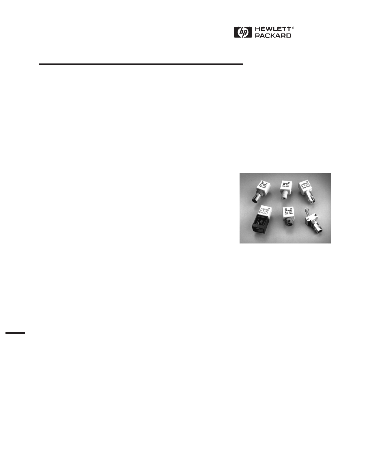
Low Cost, Miniature Fiber
Optic Components with ST®,
SMA, SC and FC Ports
Technical Data
HFBR-0400 Series
Features
• Meets IEEE 802.3 Ethernet
and 802.5 Token Ring
Standards
• Low Cost Transmitters and
Receivers
• Choice of ST®, SMA, SC or
FC Ports
• 820 nm Wavelength
Technology
• Signal Rates up to 175
Megabaud
• Link Distances up to 4 km
• Specified with 50/125 µm,
62.5/125 µm, 100/140 µm,
and 200 µm HCS® Fiber
• Repeatable ST Connections
within 0.2 dB Typical
• Unique Optical Port Design
for Efficient Coupling
• Auto-Insertable and Wave
Solderable
• No Board Mounting Hard-
ware Required
• Wide Operating
Temperature Range
-40°C to 85°C
• AlGaAs Emitters 100%
Burn-In Ensures High
Reliability
• Conductive Port Option with
the SMA and ST Threaded
Port Styles
Applications
• Local Area Networks
• Computer to Peripheral
Links
• Computer Monitor Links
• Digital Cross Connect Links
• Central Office Switch/PBX
Links
• Video Links
• Modems and Multiplexers
• Suitable for Tempest
Systems
• Industrial Control Links
Description
The HFBR-0400 Series of compo-
nents is designed to provide cost
effective, high performance fiber
optic communication links for
information systems and
industrial applications with link
distances of up to 4 kilometers.
With the HFBR-24X6, the 125
MHz analog receiver, data rates
of up to 175 megabaud are
attainable.
Transmitters and receivers are
directly compatible with popular
“industry-standard” connectors:
ST, SMA, SC and FC. They are
completely specified with
multiple fiber sizes; including
50/125 µm, 62.5/125 µm, 100/
140 µm, and 200 µm.
Complete evaluation kits are
available for ST and SMA product
offerings; including transmitter,
receiver, connectored cable, and
technical literature. In addition,
ST and SMA connectored cables
are available for evaluation.
ST® is a registered trademark of AT&T.
HCS® is a registered trademark of the SpecTran Corporation.
46
5965-1655E (1/97)
1 page 
Mechanical Dimensions
HFBR-0400 ST Series
HFBR-X41X
12.7
(0.50)
27.2
(1.07)
12.7
(0.50)
7.0
(0.28)
DIA
HFBR-X44X
3.81
(0.15)
PINS 1,4,5,8
0.51 X 0.38
(0.020 X 0.015)
PINS 2,3,6,7
0.46
(0.018)
DIA
2.54
(0.10)
PIN NO. 1
INDICATOR
8.2
(0.32)
6.35
(0.25)
3.6
(0.14)
5.1
(0.20)
10.2
(0.40)
1.27
(0.05)
2.54
(0.10)
HFBR-X46X
8.6
(0.34)
DIA
2.5 DIA PIN
(0.10) CIRCLE
4.9
(0.19)
TYP
2.4
(0.09)
TYP
12
43
7.1
(0.28)
3.6
(0.14)
MIN
NOTE 2
2.5
(0.10)
TYP
0.46 (0.018)
PIN DIA
3.0 TYP
(0.12)
2.5
(0.10)
TYP
18.6
(0.73)
7.1
(0.28)
DIA
8.2
(0.32)
7.0
(0.28) DIA
PART MARKING
2.0
(0.08)
18.6
(0.73)
8.6
(0.34)
DIA
12
43
2.5 (0.10)
DIA PIN
CIRCLE
7.1
(0.28)
NOTE 2
0.46
(0.018)
PIN
DIA
13.2
(0.52)
7.1
(0.28)
DIA
8.2
(0.32)
7.0
(0.28) DIA
9.1
(0.36)
PART MARKING
2.O
(0.08)
NOTE: ALL DIMENSIONS IN MILLIMETRES AND (INCHES).
50
5 Page 
5 MBd Logic Link Design
If resistor R1 in Figure 2 is
70.4 Ω, a forward current IF of
48 mA is applied to the HFBR-
14X4 LED transmitter. With IF =
48 mA the HFBR-14X4/24X2
logic link is guaranteed to work
with 62.5/125 µm fiber optic
cable over the entire range of 0
to 1750 meters at a data rate of
dc to 5 MBd, with arbitrary data
format and pulse width distortion
typically less than 25%. By
setting R1 = 115 Ω, the transmit-
ter can be driven with IF = 30 mA,
if it is desired to economize on
power or achieve lower pulse
distortion.
The following example will illus-
trate the technique for selecting
the appropriate value of IF and R1.
Maximum distance required
= 400 meters. From Figure 3 the
drive current should be 15 mA.
From the transmitter data
VF = 1.5 V (max.) at IF = 15 mA
as shown in Figure 9.
R1
=
V–C–C––-–V–F–
IF
=
5––V––-–1–.–5–V–
15 mA
R1 = 233␣ Ω
The curves in Figures 3, 4, and 5
are constructed assuming no in-
line splice or any additional
system loss. Should the link
consists of any in-line splices,
these curves can still be used to
calculate link limits provided they
are shifted by the additional
system loss expressed in dB. For
example, Figure 3 indicates that
with 48 mA of transmitter drive
current, a 1.75 km link distance
is achievable with 62.5/125 µm
fiber which has a maximum
attenuation of 4 dB/km. With
2 dB of additional system loss, a
1.25 km link distance is still
achievable.
Figure 2. Typical Circuit Configuration.
56
11 Page | ||
| Páginas | Total 31 Páginas | |
| PDF Descargar | [ Datasheet HFBR1412M.PDF ] | |
Hoja de datos destacado
| Número de pieza | Descripción | Fabricantes |
| HFBR1412C | Low Cost/ Miniature Fiber Optic Components with ST/ SMA/ SC and FC Ports | Agilent(Hewlett-Packard) |
| HFBR1412HA | Low Cost/ Miniature Fiber Optic Components with ST/ SMA/ SC and FC Ports | Agilent(Hewlett-Packard) |
| HFBR1412HB | Low Cost/ Miniature Fiber Optic Components with ST/ SMA/ SC and FC Ports | Agilent(Hewlett-Packard) |
| HFBR1412K | Low Cost/ Miniature Fiber Optic Components with ST/ SMA/ SC and FC Ports | Agilent(Hewlett-Packard) |
| Número de pieza | Descripción | Fabricantes |
| SLA6805M | High Voltage 3 phase Motor Driver IC. |
Sanken |
| SDC1742 | 12- and 14-Bit Hybrid Synchro / Resolver-to-Digital Converters. |
Analog Devices |
|
DataSheet.es es una pagina web que funciona como un repositorio de manuales o hoja de datos de muchos de los productos más populares, |
| DataSheet.es | 2020 | Privacy Policy | Contacto | Buscar |