|
|
|
PDF ADUM6201 Data sheet ( Hoja de datos )
| Número de pieza | ADUM6201 | |
| Descripción | (ADUM6200 - ADUM6202) Dual-Channel 5kV Isolators | |
| Fabricantes | Analog Devices | |
| Logotipo | ||
Hay una vista previa y un enlace de descarga de ADUM6201 (archivo pdf) en la parte inferior de esta página. Total 28 Páginas | ||
|
No Preview Available !
Data Sheet
Dual-Channel, 5 kV Isolators with
Integrated DC-to-DC Converter
ADuM6200/ADuM6201/ADuM6202
FEATURES
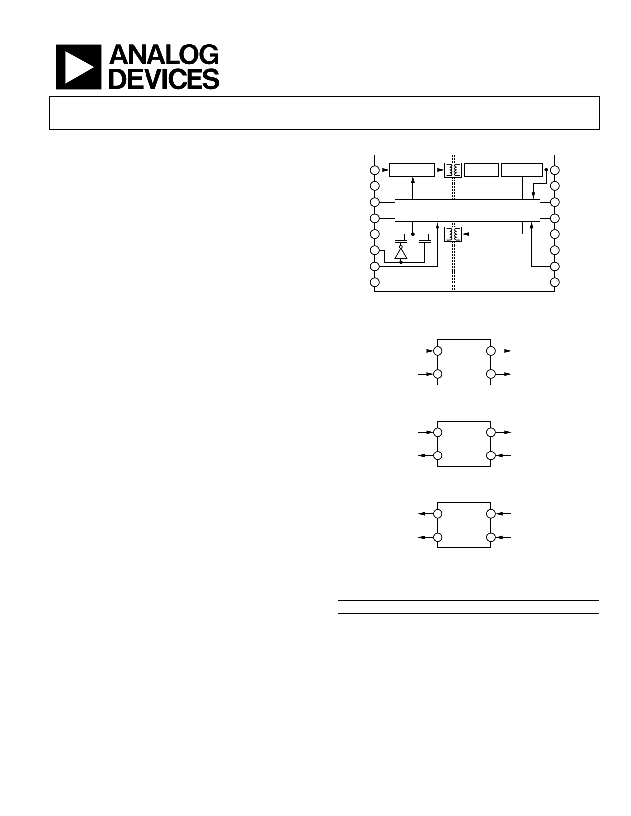
FUNCTIONAL BLOCK DIAGRAMS
isoPower integrated, isolated dc-to-dc converter
Regulated 5 V or 3.3 V output
Up to 400 mW output power
Dual dc-to-25 Mbps (NRZ) signal isolation channels
16-lead SOIC wide body package version
16-lead SOIC wide body enhanced creepage version
High temperature operation: 105°C maximum
Safety and regulatory approvals
UL recognition
5000 V rms for 1 minute per UL 1577
CSA Component Acceptance Notice #5A
IEC 60601-1: 250 V rms, 8 mm package (RI-16-1)
IEC 60950-1: 400 V rms, 8 mm package (RI-16-1)
VDE certificate of conformity (RW-16)
IEC 60747-5-2 (VDE 0884 Part 2):2003-01
VIORM = 846 V peak
VDE certificate of conformity, 8 mm package (RI-16-1)
DIN V VDE V 0884-10 (VDE V 0884-10):2006-12
VIORM = 846 V peak
APPLICATIONS
VDD1 1
OSCILLATOR
RECTIFIER REGULATOR 16 VISO
GND1 2
VIA/VOA 3
VIB/VOB 4
RCIN 5
RCSEL 6
VE1/NC 7
GND1 8
2-CHANNEL iCOUPLER CORE
ADuM6200/
ADuM6201/
ADuM6202
15 GNDISO
14 VIA/VOA
13 VIB/VOB
12 NC
11 VSEL
10 VE2/NC
9 GNDISO
NC = NO CONNECT
Figure 1.
VIA
3
VOA
14
ADuM6200
VIB VOB
4 13
Figure 2. ADuM6200
RS-232/RS-422/RS-485 transceivers
Industrial field bus isolation
Isolated sensor interfaces
Industrial PLCs
VIA
3
VOA
14
ADuM6201
VOB
VIB
4 13
GENERAL DESCRIPTION
The ADuM6200/ADuM6201/ADuM62021 are dual-channel
digital isolators with isoPower®, an integrated, isolated dc-to-dc
converter. Based on the Analog Devices, Inc., iCoupler® technology,
the dc-to-dc converter provides up to 400 mW of regulated, iso-
lated power at either 5.0 V or 3.3 V from a 5.0 V input supply, or
at 3.3 V from a 3.3 V supply at the power levels shown in Table 1.
These devices eliminate the need for a separate, isolated dc-to-dc
converter in low power, isolated designs. The iCoupler chip scale
transformer technology is used to isolate the logic signals and for
the magnetic components of the dc-to-dc converter. The result
is a small form factor, total isolation solution.
The ADuM6200/ADuM6201/ADuM6202 isolators provide two
independent isolation channels in a variety of channel configura-
tions and data rates (see the Ordering Guide for more information).
Figure 3. ADuM6201
VOA
3
VIA
14
ADuM6202
VOB
VIB
4 13
Figure 4. ADuM6202
Table 1. Power Levels
Input Voltage (V) Output Voltage (V)
5.0 5.0
5.0 3.3
3.3 3.3
Output Power (mW)
400
330
132
isoPower uses high frequency switching elements to transfer power
through its transformer. Special care must be taken during printed
circuit board (PCB) layout to meet emissions standards. See the
AN-0971 Application Note for board layout recommendations.
1 Protected by U.S. Patents 5,952,849; 6,873,065; 6,903,578; and 7,075,329; other patents are pending.
Rev. C
Information furnished by Analog Devices is believed to be accurate and reliable. However, no
responsibility is assumed by Analog Devices for its use, nor for any infringements of patents or other
rights of third parties that may result from its use. Specifications subject to change without notice. No
license is granted by implication or otherwise under any patent or patent rights of Analog Devices.
Trademarksandregisteredtrademarksarethepropertyoftheirrespectiveowners.
One Technology Way, P.O. Box 9106, Norwood, MA 02062-9106, U.S.A.
Tel: 781.329.4700
www.analog.com
Fax: 781.461.3113 ©2010–2012 Analog Devices, Inc. All rights reserved.
Free Datasheet http://www.datasheet4u.com/
1 page 
Data Sheet
ADuM6200/ADuM6201/ADuM6202
Table 7. DC-to-DC Converter Dynamic Specifications
1 Mbps—A or C Grade
Parameter
Symbol Min Typ Max
SUPPLY CURRENT
Input
ADuM6200
IDD1(D)
6
ADuM6201
7
ADuM6202
8
Available to Load
ADuM6200
IISO(LOAD)
40
ADuM6201
40
ADuM6202
40
25 Mbps—C Grade
Min Typ Max
23
25
27
36
35
34
Test Conditions/
Unit Comments
mA No VISO load
mA No VISO load
mA No VISO load
mA
mA
mA
Table 8. Switching Specifications
Parameter
A Grade
C Grade
Test Conditions/
Symbol Min Typ Max Min Typ Max Unit Comments
SWITCHING SPECIFICATIONS
Data Rate
1 25 Mbps Within PWD limit
Propagation Delay
Pulse Width Distortion
Change vs. Temperature
tPHL, tPLH
PWD
60 100
40
45 65 ns 50% input to 50% output
6 ns |tPLH − tPHL|
5 ps/°C
Pulse Width
PW 1000
40
ns Within PWD limit
Propagation Delay Skew
Channel Matching
tPSK
50 45 ns Between any two units
Codirectional1
tPSKCD
50
6 ns
Opposing Directional2
tPSKOD
50
15 ns
1 7Codirectional channel matching is the absolute value of the difference in propagation delays between any two channels with inputs on the same side of the isolation
barrier.
2 Opposing directional channel matching is the absolute value of the difference in propagation delays between any two channels with inputs on opposite sides of the
isolation barrier.
Table 9. Input and Output Characteristics
Parameter
DC SPECIFICATIONS
Logic High Input Threshold
Logic Low Input Threshold
Logic High Output Voltages
Logic Low Output Voltages
Symbol Min
VIH 0.7 × VISO or 0.7 × VDD1
VIL
VOH VDD1 − 0.3 or VISO − 0.3
VDD1 − 0.5 or VISO − 0.5
VOL
Undervoltage Lockout
Positive-Going Threshold
Negative-Going Threshold
Hysteresis
Input Currents per Channel
AC SPECIFICATIONS
Output Rise/Fall Time
Common-Mode Transient
Immunity1
Refresh Rate
UVLO
VUV+
VUV−
VUVH
II
tR/tF
|CM|
fr
−20
25
Typ
3.3
3.1
0.0
0.0
2.7
2.4
0.3
+0.01
2.5
35
1.0
Max
0.3 × VISO or 0.3 × VDD1
0.1
0.4
+20
Unit
V
V
V
V
V
V
V
V
V
µA
ns
kV/µs
Mbps
Test Conditions/
Comments
IOx = −20 µA, VIx = VIxH
IOx = −4 mA, VIx = VIxH
IOx = 20 µA, VIx = VIxL
IOx = 4 mA, VIx = VIxL
VDD1, VISO supplies
0 V ≤ VIx ≤ VDD1
10% to 90%
VIx = VDD1 or VISO, VCM = 1000 V,
transient magnitude = 800 V
1 |CM| is the maximum common-mode voltage slew rate that can be sustained while maintaining VO > 0.7 × VDD1 or 0.7 × VISO for a high input or VO < 0.3 × VDD1 or 0.3 × VISO for a low
input. The common-mode voltage slew rates apply to both rising and falling common-mode voltage edges.
Rev. C | Page 5 of 28
Free Datasheet http://www.datasheet4u.com/
5 Page 
Data Sheet
ADuM6200/ADuM6201/ADuM6202
PIN CONFIGURATIONS AND FUNCTION DESCRIPTIONS
VDD1 1
16 VISO
GND1 2
15 GNDISO
VIA 3 ADuM6200 14 VOA
VIB 4 TOP VIEW 13 VOB
RCIN 5 (Not to Scale) 12 NC
RCSEL 6
11 VSEL
NC 7
10 VE2
GND1 8
9 GNDISO
NC = NO CONNECT
Figure 6. ADuM6200 Pin Configuration
Table 21. ADuM6200 Pin Function Descriptions
Pin No.
Mnemonic Description
1 VDD1 Primary Supply Voltage, 3.0 V to 5.5 V.
2, 8
GND1
Ground Reference for the Primary Side of the Isolator. Pin 2 and Pin 8 are internally connected to each other,
and it is recommended that both pins be connected to a common ground.
3 VIA Logic Input A.
4 VIB Logic Input B.
5 RCIN Regulation Control Input. This pin must be connected to the RCOUT pin of a master isoPower device or tied low.
This pin must not be tied high if RCSEL is low; this combination causes excessive voltage on the secondary side
of the isolator, damaging the ADuM6200 and possibly the devices that it powers.
6
RCSEL
Control Input. Determines self-regulation mode (RCSEL high) or slave mode (RCSEL low), allowing external
regulation. This pin is weakly pulled to the high state. In noisy environments, tie this pin either high or low.
7, 12 NC
No Internal Connection.
9, 15
GNDISO
Ground Reference for the Secondary Side of the Isolator. Pin 9 and Pin 15 are internally connected to each
other, and it is recommended that both pins be connected to a common ground.
10 VE2 Data Enable Input. When this pin is high or not connected, the secondary outputs are active; when this pin is
low, the outputs are in a high-Z state.
11 VSEL Output Voltage Selection. When VSEL = VISO, the VISO setpoint is 5.0 V. When VSEL = GNDISO, the VISO setpoint is 3.3 V.
In slave regulation mode, this pin has no function.
13 VOB Logic Output B.
14 VOA Logic Output A.
16 VISO Secondary Supply Voltage. Output for secondary side isolated data channels and external loads.
Rev. C | Page 11 of 28
Free Datasheet http://www.datasheet4u.com/
11 Page | ||
| Páginas | Total 28 Páginas | |
| PDF Descargar | [ Datasheet ADUM6201.PDF ] | |
Hoja de datos destacado
| Número de pieza | Descripción | Fabricantes |
| ADUM6200 | (ADUM6200 - ADUM6202) Dual-Channel 5kV Isolators | Analog Devices |
| ADUM6201 | (ADUM6200 - ADUM6202) Dual-Channel 5kV Isolators | Analog Devices |
| ADUM6202 | (ADUM6200 - ADUM6202) Dual-Channel 5kV Isolators | Analog Devices |
| Número de pieza | Descripción | Fabricantes |
| SLA6805M | High Voltage 3 phase Motor Driver IC. |
Sanken |
| SDC1742 | 12- and 14-Bit Hybrid Synchro / Resolver-to-Digital Converters. |
Analog Devices |
|
DataSheet.es es una pagina web que funciona como un repositorio de manuales o hoja de datos de muchos de los productos más populares, |
| DataSheet.es | 2020 | Privacy Policy | Contacto | Buscar |