|
|
|
PDF ELM415 Data sheet ( Hoja de datos )
| Número de pieza | ELM415 | |
| Descripción | Up/Down Interface | |
| Fabricantes | ELM | |
| Logotipo | ||
Hay una vista previa y un enlace de descarga de ELM415 (archivo pdf) en la parte inferior de esta página. Total 5 Páginas | ||
|
No Preview Available !
ELM415
Up/Down Interface
Description
Many modern control circuits use the value from
a digital counter to directly determine a setting or
position. Manipulating this value under computer
control is not difficult, but when one has to interface
with a human operator, several other factors must be
considered. Human interfaces often require that the
circuit respond to changes in a setting – up or down,
left or right, clockwise or counterclockwise. These
controls need a simple interface, which the ELM415
provides.
This 8 pin integrated circuit contains all the
timing and logic that is necessary to interface two
pushbuttons to most counter type interfaces. It reads
the position of the switches and translates that into
an appropriate signal for a counter to either
increment or decrement, which in turn controls the
output variable. Logic to filter out contact bounce, to
sense when both keys are pressed simultaneously,
to invert the count output, and to provide continuous
pulses if an input pushbutton stays pressed are all
included.
Applications
• Digital audio potentiometer controls
• Variable voltage or temperature circuits
• Motor positioning controls
• Single-stepping control circuits
• Reset circuits
Features
• Low power CMOS design – typically 1mA at 5V
• Wide supply range – 3.0 to 5.5 volt operation
• Fully debounced switch inputs
• Internal pullup resistors provided
• Protection from simultaneous key presses
• High current drive outputs – up to 25 mA
• User selectable automatic repeat function
• Selectable Count output polarity
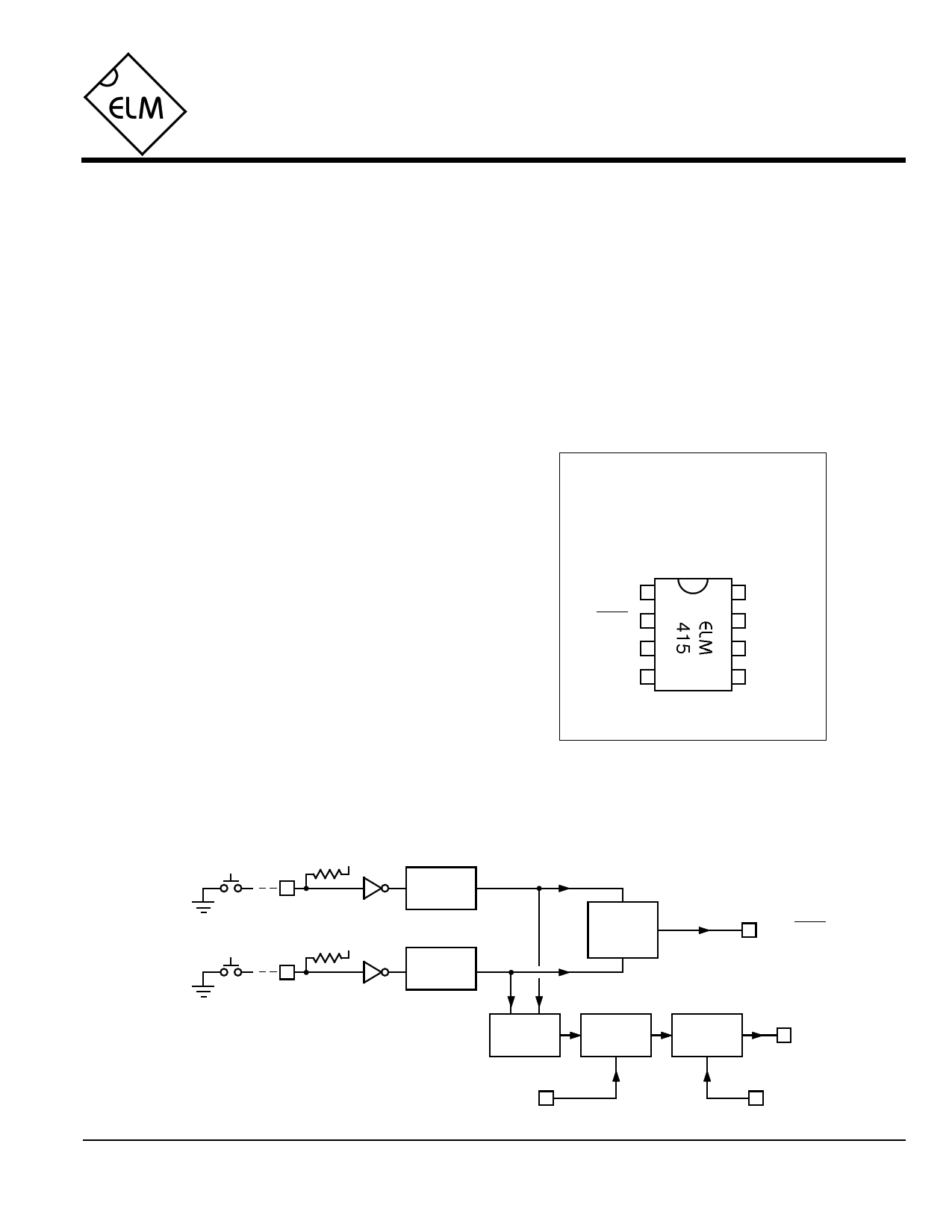
Connection Diagram
PDIP and SOIC
(top view)
VDD 1
Up/Down 2
Count 3
Invert 4
8 VSS
7 DownSw
6 UpSw
5 Repeat
Block Diagram
VDD
7
DownSw
VDD
6
UpSw
Debounce
Circuit
Debounce
Circuit
Logic
reset
Latch
set
2 Up/Down
Pulse
Generator
Output
Control
3 Count
Repeat 5
4 Invert
ELM415DSA
Elm Electronics – Circuits for the Hobbyist
< http://www.elmelectronics.com/ >
1 of 5
Free Datasheet http://www.datasheet4u.com/
1 page 
ELM415
Example Applications (cont’d)
A variation of Figure 2 is shown in Figure 3. It uses
series resistors on the pushbutton inputs, and has also
had its autorepeat function modified slightly.
This circuit assumes that the pushbuttons are to
be mounted at a distance from the ELM415, which is
why the series resistors have been added. This is a
good practice to follow whenever working with CMOS
circuits that might be exposed to electrostatically
induced charges, as could be the case due to the extra
wiring for the switches. The resistors help to limit
induced currents which will flow through the IC’s
internal protection diodes during a discharge, and in
doing so reduce the chance of latchup problems.
Generally, we recommend that protection resistors be
installed close to the IC whenever wiring is to extend
from the circuit by more than about twelve inches.
The other difference between the circuits of
Figures 2 and 3 is the connection between pins 5 and
6. This can best be explained by considering that in
Figure 3, due to the internal pullup resistor on pin 6,
pin 5 will normally be at VDD (enabling the repeat
function). When the Down button is pressed, the
autorepeat function will remain enabled, and multiple
pulses will be output. When the Up button is pressed,
however, it will pull both pins 5 and 6 low, disabling the
autorepeat and allowing only a single pulse to be
generated. This is useful if one wants the user to
explicitly press a button for each advance in one
direction, but will allow a rapid transition to a ‘safe’
position when the other button is pressed. This may be
a desireable feature if controlling the temperature in a
heater circuit, for example.
1KΩ
1KΩ
Up
Down
5
6
7
8
4
3
2
VDD
1
VDD
18
2 AD5220 7
36
45
Figure 3. Controlling a digital potentiometer (with rapid down)
Our final example shows how easily one can use
the ELM415 as a ‘one-shot’ or monostable
multivibrator in a reset circuit. Often one has the need
to reset a circuit using a pushbutton, but multiple
Reset
5
6
7
8
4
Reset
3
Output
2
VDD
1
resets due to bouncing switches would be an
annoyance. Using the circuit of Figure 4, one can
generate a single clean reset pulse whenever the
pushbutton is pressed. If the circuit needs a negative-
going pulse, simply connect pin 4 to VDD rather than
VSS.
Hopefully this has provided you with several ideas
for using the ELM415 in your next project. Have you
considered using it to reset a timer whenever a contact
closes, or to count switch closures, or to determine an
object’s direction based on the order in which the two
switches operated…
Figure 4. Manual reset circuit
ELM415DSA
Elm Electronics – Circuits for the Hobbyist
< http://www.elmelectronics.com/ >
5 of 5
Free Datasheet http://www.datasheet4u.com/
5 Page | ||
| Páginas | Total 5 Páginas | |
| PDF Descargar | [ Datasheet ELM415.PDF ] | |
Hoja de datos destacado
| Número de pieza | Descripción | Fabricantes |
| ELM410 | Triple Debounce Circuit | ELM |
| ELM411 | Debounce Circuit | ELM |
| ELM412 | Piezo Element Driver | ELM |
| ELM413 | LED Driver | ELM |
| Número de pieza | Descripción | Fabricantes |
| SLA6805M | High Voltage 3 phase Motor Driver IC. |
Sanken |
| SDC1742 | 12- and 14-Bit Hybrid Synchro / Resolver-to-Digital Converters. |
Analog Devices |
|
DataSheet.es es una pagina web que funciona como un repositorio de manuales o hoja de datos de muchos de los productos más populares, |
| DataSheet.es | 2020 | Privacy Policy | Contacto | Buscar |