|
|
|
PDF HIP6007 Data sheet ( Hoja de datos )
| Número de pieza | HIP6007 | |
| Descripción | Buck Pulse-Width Modulator (PWM) Controller | |
| Fabricantes | Intersil Corporation | |
| Logotipo | ||
Hay una vista previa y un enlace de descarga de HIP6007 (archivo pdf) en la parte inferior de esta página. Total 10 Páginas | ||
|
No Preview Available !
Data Sheet
HIP6007
September 1997 File Number 4307.1
Buck Pulse-Width Modulator (PWM)
Controller
The HIP6007 provides complete control and protection for
a DC-DC converter optimized for high-performance
microprocessor applications. It is designed to drive an
N-Channel MOSFET in a standard buck topology. The
HIP6007 integrates all of the control, output adjustment,
monitoring and protection functions into a single package.
The output voltage of the converter can be precisely
regulated to as low as 1.27V, with a maximum tolerance of
±1% over temperature and line voltage variations.
The HIP6007 provides simple, single feedback loop, voltage-
mode control with fast transient response. It includes a
200kHz free-running triangle-wave oscillator that is
adjustable from below 50kHz to over 1MHz. The error
amplifier features a 15MHz gain-bandwidth product and
6V/µs slew rate which enables high converter bandwidth for
fast transient performance. The resulting PWM duty ratio
ranges from 0% to 100%.
The HIP6007 protects against over-current conditions by
inhibiting PWM operation. The HIP6007 monitors the current
by using the rDS(ON) of the upper MOSFET which eliminates
the need for a current sensing resistor.
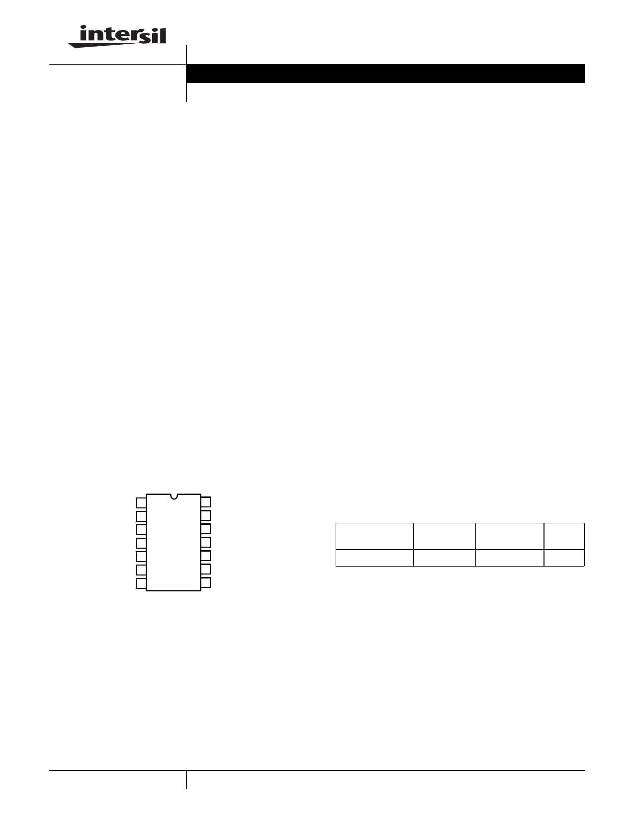
Pinout
HIP6007
(SOIC)
TOP VIEW
RT 1
OCSET 2
SS 3
COMP 4
FB 5
EN 6
GND 7
14 VCC
13 NC
12 NC
11 NC
10 BOOT
9 UGATE
8 PHASE
Features
• Drives N-Channel MOSFET
• Operates From +5V or +12V Input
• Simple Single-Loop Control Design
- Voltage-Mode PWM Control
• Fast Transient Response
- High-Bandwidth Error Amplifier
- Full 0% to 100% Duty Ratio
• Excellent Output Voltage Regulation
- 1.27V Internal Reference
- ±1% Over Line Voltage and Temperature
• Over-Current Fault Monitor
- Does Not Require Extra Current Sensing Element
- Uses MOSFET’s rDS(on)
• Small Converter Size
- Constant Frequency Operation
- 200kHz Free-Running Oscillator Programmable from
50kHz to Over 1MHz
• 14 Pin, SOIC Package
Applications
• Power Supply for Pentium®, Pentium Pro, PowerPC™ and
Alpha™ Microprocessors
• High-Power 5V to 3.xV DC-DC Regulators
• Low-Voltage Distributed Power Supplies
Ordering Information
TEMP. RANGE
PART NUMBER
(oC)
PACKAGE
HIP6007CB
0 to 70 14 Ld SOIC
PKG.
NO.
M14.15
2-131
PowerPC™ is a trademark of IBM.
Alpha™ is a trademark of Digital Equipment Corporation.
Pentium® is a registered trademark of Intel Corporation.
CAUTION: These devices are sensitive to electrostatic discharge; follow proper IC Handling Procedures.
http://www.intersil.com or 407-727-9207 | Copyright © Intersil Corporation 1999
1 page 
HIP6007
Functional Description
Initialization
The HIP6007 automatically initializes upon receipt of power.
Special sequencing of the input supplies is not necessary.
The Power-On Reset (POR) function continually monitors
the input supply voltages and the enable (EN) pin. The POR
monitors the bias voltage at the VCC pin and the input
voltage (VIN) on the OCSET pin. The level on OCSET is
equal to VIN less a fixed voltage drop (see over-current
protection). With the EN pin held to VCC, the POR function
initiates soft start operation after both input supply voltages
exceed their POR thresholds. For operation with a single
+12V power source, VIN and VCC are equivalent and the
+12V power source must exceed the rising VCC threshold
before POR initiates operation.
The Power-On Reset (POR) function inhibits operation with
the chip disabled (EN pin low). With both input supplies
above their POR thresholds, transitioning the EN pin high
initiates a soft start interval.
Soft Start
The POR function initiates the soft start sequence. An internal
10µA current source charges an external capacitor (CSS) on
the SS pin to 4V. Soft start clamps the error amplifier output
(COMP pin) and reference input (+ terminal of error amp) to
the SS pin voltage. Figure 3 shows the soft start interval with
CSS = 0.1µF. Initially the clamp on the error amplifier (COMP
pin) controls the converter’s output voltage. At t1 in Figure 3,
the SS voltage reaches the valley of the oscillator’s triangle
wave. The oscillator’s triangular waveform is compared to the
ramping error amplifier voltage. This generates PHASE
pulses of increasing width that charge the output capacitor(s).
This interval of increasing pulse width continues to t2. With
sufficient output voltage, the clamp on the reference input
controls the output voltage. This is the interval between t2 and
t3 in Figure 3. At t3 the SS voltage exceeds the reference
voltage and the output voltage is in regulation. This method
provides a rapid and controlled output voltage rise.
SOFT-START
(1V/DIV)
OUTPUT
VOLTAGE
0V (1V/DIV)
0V
t1 t2
t3
TIME (5ms/DIV)
FIGURE 3. SOFT-START INTERVAL
Over-Current Protection
The over-current function protects the converter from a
shorted output by using the upper MOSFET’s on-resistance,
rDS(ON) to monitor the current. This method enhances the
converter’s efficiency and reduces cost by eliminating a
current sensing resistor.
The over-current function cycles the soft-start function in a
hiccup mode to provide fault protection. A resistor (ROCSET)
programs the over-current trip level. An internal 200µA
(typical) current sink develops a voltage across ROCSET that
is reference to VIN. When the voltage across the upper
MOSFET (also referenced to VIN) exceeds the voltage
across ROCSET, the over-current function initiates a soft-
start sequence. The soft-start function discharges CSS with
a 10µA current sink and inhibits PWM operation. The soft-
start function recharges CSS, and PWM operation resumes
with the error amplifier clamped to the SS voltage. Should an
overload occur while recharging CSS, the soft start function
inhibits PWM operation while fully charging CSS to 4V to
complete its cycle. Figure 4 shows this operation with an
overload condition. Note that the inductor current increases
to over 15A during the CSS charging interval and causes an
over-current trip. The converter dissipates very little power
with this method. The measured input power for the
conditions of Figure 4 is 2.5W.
2-135
5 Page | ||
| Páginas | Total 10 Páginas | |
| PDF Descargar | [ Datasheet HIP6007.PDF ] | |
Hoja de datos destacado
| Número de pieza | Descripción | Fabricantes |
| HIP6002 | Rectifier (PWM) Controller and Output Voltage Monitor | Intersil Corporation |
| HIP6002CB | Rectifier (PWM) Controller and Output Voltage Monitor | Intersil Corporation |
| HIP6003 | Buck Pulse-Width Modulator (PWM) Controller and Output Voltage Monitor | Intersil Corporation |
| HIP6003CB | Buck Pulse-Width Modulator (PWM) Controller and Output Voltage Monitor | Intersil Corporation |
| Número de pieza | Descripción | Fabricantes |
| SLA6805M | High Voltage 3 phase Motor Driver IC. |
Sanken |
| SDC1742 | 12- and 14-Bit Hybrid Synchro / Resolver-to-Digital Converters. |
Analog Devices |
|
DataSheet.es es una pagina web que funciona como un repositorio de manuales o hoja de datos de muchos de los productos más populares, |
| DataSheet.es | 2020 | Privacy Policy | Contacto | Buscar |