|
|
|
PDF HIP1015 Data sheet ( Hoja de datos )
| Número de pieza | HIP1015 | |
| Descripción | Power Distribution Controllers | |
| Fabricantes | Intersil Corporation | |
| Logotipo | ||
Hay una vista previa y un enlace de descarga de HIP1015 (archivo pdf) en la parte inferior de esta página. Total 10 Páginas | ||
|
No Preview Available !
TM
Data Sheet
HIP1015, HIP1016
May 2000 File Number 4778.1
Power Distribution Controllers
The HIP1015 and HIP1016 are hot swap power controllers.
The HIP1015 is targeted for a +12V bus whereas the
HIP1016 is targeted for +5V applications. Each has an
undervoltage (UV) monitoring and reporting with a threshold
level ~17% lower than the nominal +12V and +5V.
The HIP1015 has an integrated charge pump allowing
control of up to a +12V bus using an external N-channel
MOSFET. The HIP1016 can also be used to control much
higher positive or negative voltages in a low side controller
configuration. Both the HIP1015 and HIP1016 feature
programmable Overcurrent (OC) detection, current limiting
regulation with time delay to latch off and soft start.
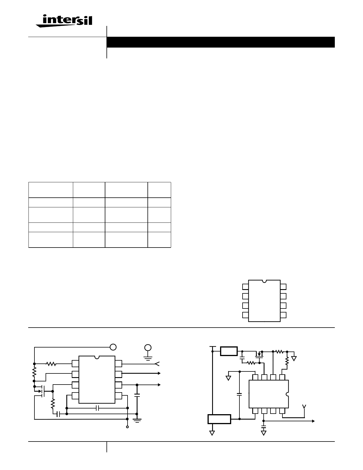
Ordering Information
PART NUMBER
HIP1015CB
HIP1015CB-T
HIP1016CB
HIP1016CB-T
TEMP.
RANGE (oC)
PACKAGE
0 to 85 8 Lead SOIC
0 to 85
8 Lead SOIC
Tape and Reel
0 to 85 8 Lead SOIC
0 to 85
8 Lead SOIC
Tape and Reel
PKG.
NO.
M8.15
M8.15
M8.15
M8.15
Application One - High Side Controller
+ LOAD -
18
27
HIP1015
36
45
PWRON
PGOOD
OC
+12V
Features
• HOT SWAP Single Power Distribution Control (HIP1015
for 12V, HIP1016 for 5V and Low Side Switch)
• Undervoltage Monitoring and Notification
• Overcurrent Fault Isolation
• Programmable Current Regulation Level
• Programmable Current Limit Time to Latch-Off
• Rail to Rail Common Mode Input Voltage Range
(HIP1015)
• Internal Charge Pump Allows the use of N-channel
MOSFET (HIP1015)
• Undervoltage and Overcurrent Latch Indicators
• Adjustable Turn-On Ramp
• Protection During Turn On
• Two Levels of Overcurrent Detection Provide Fast
Response to Varying Fault Conditions
• Less Than 1µs Response Time to Dead Short
Applications
• Power Distribution Control
• Hot Plug Components and Circuitry
• High Side Low Voltage (< +15V) Switching
• Low Side High Voltage (> +15V, Negative V) Switch
Pinout
HIP1015, HIP1016 (SOIC)
TOP VIEW
ISET 1
ISEN 2
GATE 3
VSS 4
8 PWRON
7 PGOOD
6 CTIM
5 VDD
Application Two - Low Side Controller
+VBUS
LOAD
12V REG
HIP1016
PWRON
OC
1
CAUTION: These devices are sensitive to electrostatic discharge; follow proper IC Handling Procedures.
1-888-INTERSIL or 321-724-7143 | Intersil and Design is a trademark of Intersil Corporation. | Copyright © Intersil Corporation 2000
1 page 
HIP1015, HIP1016
Physical layout of RSENSE resistor is critical to avoid the
possibility of false overcurrent occurrences. Ideally trace
routing between the RSENSE resistors and the HIP1015 and
HIP1016 is direct and as short as possible with zero current
in the sense lines. (See Figure 1.)
CORRECT
INCORRECT
TO ISEN AND
RISET
CURRENT
SENSE RESISTOR
FIGURE 1. SENSE RESISTOR PCB LAYOUT
Using the HIP1016 as a -48V Low Side Hot
Swap Power Controller
To supply the required VDD, it is necessary to maintain the
chip supply 12V above the -48V bus. This may be
accomplished with a +12V Regulator between the voltage
rail and pin 5 (VDD). By using a Regulator, the designer may
ignore the bus voltage variations. However, a low-cost
alternative is to use a Zener diode (See Figure 2 for typical
5A load control ) this option is detailed below.
Note that in this configuration the PGOOD feature (pin 7) is
not operational.
RCL
1.58kΩ
1W
LOAD
0.001µF
HUF7554S3S
0.005
1%
1.47kΩ
1%
2kΩ
0.01µF
HIP1016
DD1
12V 0.047µF
VBUS -48V
FIGURE 2.
NC
PWRON
Biasing the HIP1016
Table 3 gives typical component values for biasing the
HIP1016 in a 48V application. The formulas and calculations
deriving these values are also shown below.
TABLE 3. TYPICAL VALUES FOR A -48V HOT SWAP
APPLICATION
SYMBOL
PARAMETER
RCL
DD1
1.58kΩ, 1W
12V Zener Diode, 50mA Reverse Current
When using the HIP1016 to control -48V, a Zener diode may
be used to provide the +12V bias to the chip. If a Zener is
used then a current limit resistor should also be used.
Several items must be taken into account when choosing
values for the current limit resistor (RCL) and Zener Diode
(DD1):
• The variation of the VBUS (in this case, -48V)
• The chip supply current needs for all functional conditions
• The power rating of RCL.
• The current rating of DD1
Formulas
1. Sizing RCL:
RCL = (VBUS,MIN - 12)/ICHIP
2. Power Rating of RCL:
PRCL = IC(VBUS,MAX - 12)
3. DD1 Current Rating:
IDD1 = (VBUS,MAX - 12)/RCL
Example:
A typical -48V supply may vary from -36 to -72V. Therefore,
VBUS,MAX = -72V
VBUS,MIN = -36V
ICHIP = 15mA (max)
Sizing RCL:
RCL = (VBUS,MIN - 12)/IC
RCL = (36 - 12)/0.015
RCL = 1.6kΩ [Typical Value = 1.58kΩ]
Power Rating of RCL:
PRCL = IC(VBUS,MAX - 12)
PRCL = (0.015)(72 - 12)
PRCL = 0.9W [Typical Value = 1W]
DD1 Current Rating:
IDD1 = (VBUS,MAX - 12)/RCL
IDD1 = (72 - 12)/1.58kΩ
IDD1 = 38mA [Typical Value = 12V rating, 50mA reverse
current]
5
5 Page | ||
| Páginas | Total 10 Páginas | |
| PDF Descargar | [ Datasheet HIP1015.PDF ] | |
Hoja de datos destacado
| Número de pieza | Descripción | Fabricantes |
| HIP1011 | PCI Hot Plug Controller | Intersil Corporation |
| HIP1011A | PCI Hot Plug Controller | Intersil Corporation |
| HIP1011B | PCI Hot Plug Controller | Intersil Corporation |
| HIP1011D | Dual PCI Hot Plug Controller | Intersil Corporation |
| Número de pieza | Descripción | Fabricantes |
| SLA6805M | High Voltage 3 phase Motor Driver IC. |
Sanken |
| SDC1742 | 12- and 14-Bit Hybrid Synchro / Resolver-to-Digital Converters. |
Analog Devices |
|
DataSheet.es es una pagina web que funciona como un repositorio de manuales o hoja de datos de muchos de los productos más populares, |
| DataSheet.es | 2020 | Privacy Policy | Contacto | Buscar |