|
|
|
PDF RF68 Data sheet ( Hoja de datos )
| Número de pieza | RF68 | |
| Descripción | Low Cost Integrated Transmitter IC | |
| Fabricantes | HOPERF | |
| Logotipo | ||
Hay una vista previa y un enlace de descarga de RF68 (archivo pdf) en la parte inferior de esta página. Total 21 Páginas | ||
|
No Preview Available !
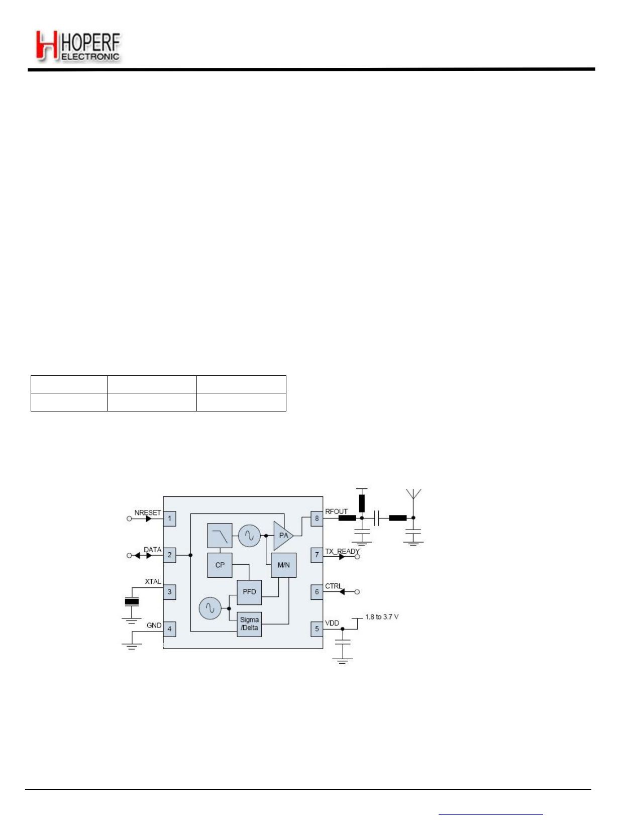
RF68 - Low Cost Integrated Transmitter IC
310 to 928MHz Frequency Agile
RF68
GENERAL DESCRIPTION
The RF68 is an ultra-low-cost, fully integrated FSK or
OOK transmitter suitable for operation between 310 and
450 MHz, 860 and 870 MHz, as well as 902 and 928 MHz.
For applications where economy is paramount, the RF68
may be used without the requirement for configuration via
an MCU. However, in conjunction with a microcontroller the
communication link parameters may be re-configured.
Including, output power, modulation format and operating
channel.
The RF68 offers integrated radio performance with cost
efficiency and is suited for operation in North America FCC
part 15.231, FCC part 15.247 DTS and FHSS modes,
15.249, and Europe EN 300 220.
ORDERING INFORMATION
Part Number
RF68
Temperature Range
-40 °C to +85 °C
Package
DFN8
Pb-Free, Halogen Free, RoHS/WEEE compliant product.
APPLICATIONS
Garage Door Openers
Low-Cost Consumer Electronic Applications
Remote Keyless Entry (RKE)
Remote Control / Security Systems
KEY PRODUCT FEATURES
+10 dBm or 0 dBm Configurable output power
Bit rates up to 100 kbps
OOK and FSK modulation.
1.8 to 3.7 V supply range.
Low BOM Fully Integrated Tx
Fractional-N PLL with 1.5 kHz typical step
Frequency agility for FHSS modulation
FCC Part 15.247 DTS Mode compliant
Page 1
Tel: +86-755-82973805 Fax: +86-755-82973550 E-mail: [email protected] http://www.hoperf.com
Free Datasheet http://www.datasheet4u.com/
1 page 
2. Electrical Characteristics
2.1. ESD Notice
The RF68 is an electrostatic discharge sensitive device. It satisfies Class 2 of the JEDEC standard
JESD22-A114-B (human body model) on all pins.
RF68
2.2. Absolute Maximum Ratings
Stresses above the values listed below may cause permanent device failure. Exposure to absolute maximum ratings for
extended periods may affect device reliability.
Table 2 Absolute Maximum Ratings
Symbol
VDDmr
Tmr
Tjunc
Tstor
Supply Voltage
Temperature
Junction Temperature
Storage Temperature
Description
Min Max Unit
-0.5 3.9 V
-55 115 °C
-55 125 °C
-55 150 °C
2.3. Operating Range
Operating ranges define the limits for functional operation and the parametric characteristics of the device as described in
this section. Functionality outside these limits is not implied.
Table 3 Operating Range
Symbol
VDDop
Top
Clop
Description
Supply voltage
Operational temperature range
Load capacitance on digital ports
Min Max Unit
1.8 3.7 V
-40 85 °C
- 25 pF
Page 5
Tel: +86-755-82973805 Fax: +86-755-82973550 E-mail: [email protected] http://www.hoperf.com
Free Datasheet http://www.datasheet4u.com/
5 Page 
RF68
4.5. Frequency Band Coverage
The RF68 offers several combinations or frequency references and frequency outputs, allowing for maximum flexibility
and design of multi-band products:
Table 7 Frequency Selection Table
Reference
Frequency
FXOSC
Band Setting
DA(13)
Upper / Lower
Frequency
Bounds
22 MHz
310 to 450 MHz
Fstep
Fstep= 2----2--2-x--1-1-4--0---6-= 1.34277kHz
Frf &
Fdev
24 MHz
0
312 to 450 MHz
Fstep= 2----4--2-x--1-1-4--0---6-= 1.46484kHz
Frf= DF(18;0) ×Fstep
26 MHz
338 to 450 MHz
Fstep= 2----6---x---1---0---6-= 1.58691kHz Fdev= DA(12;5) ×Fstep
214
1
860 to 870 MHz
and
Fstep=
2---6----x---1---0---6-
213
=
3.17383 k H z
902 to 928 MHz
4.6. Power Consumption
The following typical power consumption figures are observed on the RF68 kits. Note that the transmitter efficiency
depends on the impedance matching quality, and can be PCB design dependant.
The PA matching may be different in each frequency band.
Table 8 Power Consumption in Tx mode
Frequency Band Conditions
310 to 450 MHz
860 to 870 MHz
902 to 928 MHz
Pout=+10dBm, OOK modulation with 50% duty cycle
Pout=+10dBm, FSK modulation
Pout=0dBm, FSK modulation
Pout=+10dBm, FSK modulation
Pout=0dBm, FSK modulation
Pout=+10dBm, FSK modulation
Pout=0dBm, FSK modulation
Typical Current
Drain
11 mA
15 mA
9 mA
16.5 mA
10 mA
17.5 mA
10.5 mA
Page 11
Tel: +86-755-82973805 Fax: +86-755-82973550 E-mail: [email protected] http://www.hoperf.com
Free Datasheet http://www.datasheet4u.com/
11 Page | ||
| Páginas | Total 21 Páginas | |
| PDF Descargar | [ Datasheet RF68.PDF ] | |
Hoja de datos destacado
| Número de pieza | Descripción | Fabricantes |
| RF6001 | FRACTIONAL-N RF SYNTHESIZER WITH MODULATOR AND DIGITAL IF FILTER | RF Micro Devices |
| RF6001PCBA | FRACTIONAL-N RF SYNTHESIZER WITH MODULATOR AND DIGITAL IF FILTER | RF Micro Devices |
| RF600D | RF / IR Encoder / Decoder Chipset RF Evaluation Boards | rfsolutions |
| RF600E | RF / IR Encoder / Decoder Chipset RF Evaluation Boards | rfsolutions |
| Número de pieza | Descripción | Fabricantes |
| SLA6805M | High Voltage 3 phase Motor Driver IC. |
Sanken |
| SDC1742 | 12- and 14-Bit Hybrid Synchro / Resolver-to-Digital Converters. |
Analog Devices |
|
DataSheet.es es una pagina web que funciona como un repositorio de manuales o hoja de datos de muchos de los productos más populares, |
| DataSheet.es | 2020 | Privacy Policy | Contacto | Buscar |