|
|
|
PDF ACT8712 Data sheet ( Hoja de datos )
| Número de pieza | ACT8712 | |
| Descripción | Four Channel Integrated Power Management IC | |
| Fabricantes | Active-Semi | |
| Logotipo | ||
Hay una vista previa y un enlace de descarga de ACT8712 (archivo pdf) en la parte inferior de esta página. Total 30 Páginas | ||
|
No Preview Available !
ACT8712
Rev0, 25-Feb-08
Advanced Product Information―All Information Subject to Change
Four Channel Integrated Power Management IC
for Handheld Portable Equipment
FEATURES
• Multiple Patents Pending
• Li+ Battery Charger with Integrated MOSFET
− Programmable Charge Current up to 1A
− ON/OFF Control and Status Indication
• Three Integrated Regulators
− 550mA Step-Down DC/DC
− 750mA Step-Down DC/DC
− Step-Up DC/DC with OVP for WLED Bias
• I2CTM Compatible Serial Interface
− Programmable Output Voltages
− Configurable Operating Modes
• Minimal External Components
• 4x4mm, Thin-QFN (TQFN44-24) Package
− Only 0.75mm Height
− RoHS Compliant
APPLICATIONS
• Portable Devices and PDAs
• Digital Media Players
• Battery Operated Devices
• GPS Receivers, etc.
GENERAL DESCRIPTION
The patent-pending ACT8712 is a complete, cost
effective, highly efficient ActivePMUTM power man-
agement solution that is ideal for a wide range of
portable handheld equipment. This device inte-
grates two PWM step-down DC/DC converters, one
PWM step-up DC/DC converter with over-voltage
protection (OVP) and a full-featured linear-mode
Li+ battery charger into a single, thin, space-saving
package. An I2C Serial Interface provides program-
mability for the DC/DC converters and battery
charger.
REG1 and REG2 are fixed-frequency, current-mode
PWM step-down DC/DC converters that are opti-
mized for high efficiency and are capable of supply-
ing up to 550mA and 750mA, respectively. REG3 is
a fixed-frequency PWM step-up converter that
safely and efficiently biases a string of up to seven
white-LEDs for backlighting. The battery charger
incorporates an internal power MOSFET for con-
stant-current/constant-voltage, thermally regulated
charging of a single-cell Li+ battery. All DC/DC con-
verters’ output voltage are programmable and con-
trollable via the I2C interface.
The ACT8712 is available in a tiny 4mm x 4mm
24-pin Thin-QFN package that is just 0.75mm thin.
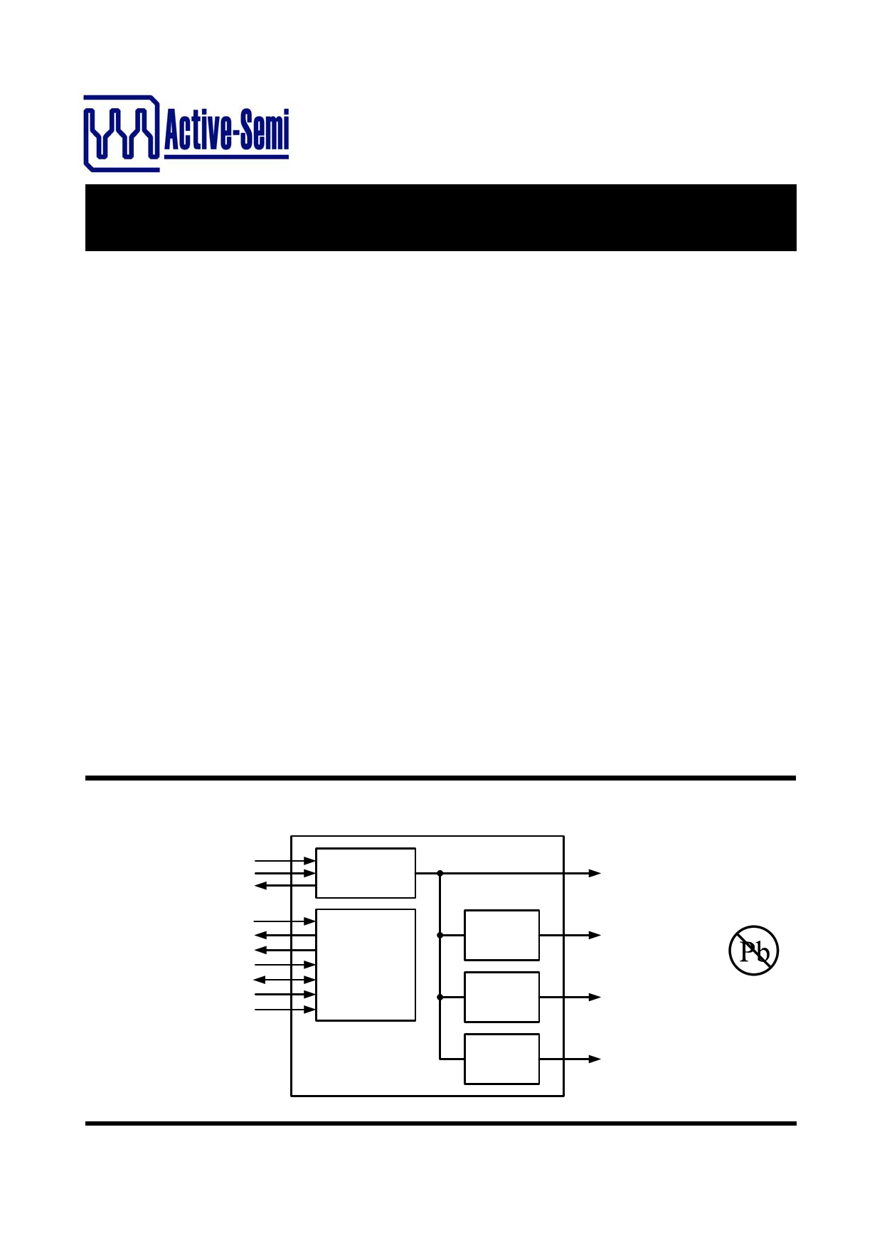
SYSTEM BLOCK DIAGRAM
VIN
CHGLEV
nSTAT
nMSTR
nIRQ
nRSTO
SCL
SDA
ON1
ON2
Single-Cell Li+
Battery Charger
System Control
ACT8712
PMUActive
TM
REG1
Step-Down
DC/DC
REG2
Step-Down
DC/DC
REG3
Step-Up
DC/DC
Battery
Programmable
Up to 1A
OUT1
1.1V to 4.4V
Up to 550mA
OUT2
1.1V to 4.4V
Up to 750mA
OUT3
WLED Bias
Pb-free
Innovative Products. Active Solutions.
ActivePMUTM is a trademark of Active-Semi.
I2CTM is a trademark of Philips Electronics.
-1-
www.active-semi.com
Copyright © 2008 Active-Semi, Inc.
Free Datasheet http://www.datasheet4u.com/
1 page 
ACT8712
Rev0, 25-Feb-08
PIN DESCRIPTIONS
PIN NAME
DESCRIPTION
Power Input for the Battery Charger. Bypass VIN to GA with a capacitor placed as close to
1 VIN the IC as possible. The battery charger and both step-down DC/DCs (REG1 and REG2)
are automatically enabled when a valid voltage is present on VIN.
2 SCL Clock Input for I2C Serial Interface. Data is read on the rising edge of the clock.
3 SDA Data Input for I2C Serial Interface. Data is read on the rising edge of the clock.
4
nIRQ
Open-Drain Push-Button Status Output. nIRQ is an open-drain output which sinks current
when nMSTR is asserted.
5 nMSTR Master Enable Input. Drive nMSTR to GA or to a logic low to enable IC.
6
nRSTO
Open-Drain Reset Output. nRSTO asserts low for the reset timeout period of 300ms when-
ever the IC is enabled.
7
OUT1
Output Feedback Sense for REG1. Connect this pin directly to the output node to connect
the internal feedback network to the output voltage.
8
VP1
Power Input for REG1. Bypass to GP12 with a high quality ceramic capacitor placed as
close as possible to the IC.
9 SW1 Switching Node Output for REG1. Connect this pin to the switching end of the inductor.
10
GP12
Power Ground for REG1 and REG2. Connect GA, GP12, and GP3 together at a single
point as close to the IC as possible.
11 SW2 Switching Node Output for REG2. Connect this pin to the switching end of the inductor.
12
VP2
Power Input for REG2. Bypass to GP12 with a high quality ceramic capacitor placed as
close as possible to the IC.
13
OUT2
Output Feedback Sense for REG2. Connect this pin directly to the output node to connect
the internal feedback network to the output voltage.
Enable Control Input for REG3. ON2 is functional only when ON1 is driven high, nMSTR is
14 ON2 driven low, or when a valid supply voltage is present on VIN. Drive ON2 to VSYS or to a
logic high for normal operation, drive to GA or a logic low to disable REG3.
15
ON1
Enable Control Input for REG1 and REG2. Drive ON1 to VSYS or to a logic high for normal
operation, drive to GA or to a logic low to disable REG1 and REG2.
Power Bypass for System Management Circuitry. Bypass to GA with a high quality ceramic
16 VSYS capacitor placed as close as possible to the IC. VSYS is internally connected to the higher
voltage of either VVIN or VBAT. Do not load VSYS with more than 100µA.
Innovative Products. Active Solutions.
ActivePMUTM is a trademark of Active-Semi.
I2CTM is a trademark of Philips Electronics.
-5-
www.active-semi.com
Copyright © 2008 Active-Semi, Inc.
Free Datasheet http://www.datasheet4u.com/
5 Page 
ACT8712
Rev0, 25-Feb-08
SYSTEM MANAGEMENT
TYPICAL PERFORMANCE CHARACTERISTICS
(VVSYS = 3.6V, TA = 25°C, unless otherwise specified.)
Oscillator Frequency vs. Temperature
1.71
1.68
1.65
1.62
1.59
1.56
1.53
1.50
-40
-20 0
20 40
Temperature (°C)
60
85
VSYS Current vs. Temperature
3
ON1 = ON2 = GA
VVSYS = 4.2V
2
VVSYS = 3.6V
1 VVSYS = 3.2V
0
-40 -20 0
20 40 60
Temperature (°C)
85
Startup Sequence
CH1
CH2
CH3
CH4
CH1: VnMSTR, 5V/div
CH2: VnRSTO, 2V/div
CH3: VON1, 5V/div
CH4: VOUT1, 2V/div
TIME: 100ms/div
Shutdown Sequence
CH1
CH2
CH3
CH4
CH1: VnMSTR, 5V/div
CH2: VnRSTO, 2V/div
CH3: VON1, 5V/div
CH4: VOUT1, 2V/div
TIME: 100ms/div
Innovative Products. Active Solutions.
ActivePMUTM is a trademark of Active-Semi.
I2CTM is a trademark of Philips Electronics.
- 11 -
www.active-semi.com
Copyright © 2008 Active-Semi, Inc.
Free Datasheet http://www.datasheet4u.com/
11 Page | ||
| Páginas | Total 30 Páginas | |
| PDF Descargar | [ Datasheet ACT8712.PDF ] | |
Hoja de datos destacado
| Número de pieza | Descripción | Fabricantes |
| ACT8712 | Four Channel Integrated Power Management IC | Active-Semi |
| Número de pieza | Descripción | Fabricantes |
| SLA6805M | High Voltage 3 phase Motor Driver IC. |
Sanken |
| SDC1742 | 12- and 14-Bit Hybrid Synchro / Resolver-to-Digital Converters. |
Analog Devices |
|
DataSheet.es es una pagina web que funciona como un repositorio de manuales o hoja de datos de muchos de los productos más populares, |
| DataSheet.es | 2020 | Privacy Policy | Contacto | Buscar |